
Multiband metal back cover integrated MIMO (multiple input multiple output) mobile phone antenna

A metal back cover, mobile phone antenna technology, applied to antenna equipment, antennas, antenna parts and other directions with additional functions, can solve the problems of antenna radiation efficiency reduction, antenna influence, antenna design difficulties, etc., to achieve the realization of operating frequency and frequency Bandwidth, ease of built-in integration, and aesthetically pleasing effects

Inactive Publication Date: 2017-01-25
SHANGHAI UNIV
View PDF5 Cites 4 Cited by
  • Summary
  • Abstract
  • Description
  • Claims
  • Application Information

AI Technical Summary

Problems solved by technology

These metal parts have a great impact on the performance of the antenna, which will narrow the operating bandwidth of the antenna or even have no resonance at all at low frequencies, which has caused great difficulties in antenna design.
In order to allow the antenna to cover a large amount of bandwidth, the metal frame is cut and slit, which will seriously affect the appearance of the mobile phone, or switch several times at the appropriate position, which will increase the loss of the antenna and reduce the radiation efficiency of the antenna.

Method used


Image

  • Multiband metal back cover integrated MIMO (multiple input multiple output) mobile phone antenna
  • Multiband metal back cover integrated MIMO (multiple input multiple output) mobile phone antenna
  • Multiband metal back cover integrated MIMO (multiple input multiple output) mobile phone antenna

Examples


Embodiment Construction

[0020] Preferred embodiments of the present invention are described in detail as follows in conjunction with accompanying drawings:

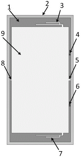
[0021] see figure 1 , a MIMO mobile phone antenna integrated with a multi-band metal back cover, including a dielectric board 1, a metal frame 2, an L-shaped radiation upper branch 3, an upper feed point 4, a right short-circuit point 5, a lower feed point 6, and an L-shaped radiation The lower branch 7, the left short-circuit point 8, and the metal back cover 9, the dielectric board 1 is integrated on the metal back cover 9, the metal frame 2 is fully enclosed and fixed on the outside of the media board 1, and the metal back cover 9 and There is a gap between the metal frame 2; the metal frame 2 and the dielectric plate 1 are divided into two symmetrical upper and lower parts by the right short-circuit point 5 and the left short-circuit point 8, and the upper feed point 4 and the lower feed point 6 are distributed at the right short-circuit poi...


PUM


Abstract

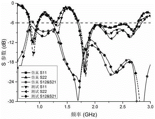
The invention relates to a multiband metal back cover integrated MIMO (multiple input multiple output) mobile phone antenna which comprises a dielectric plate, a metal frame, an L-shaped upper radiation branch node, an upper feeding point, a right short-circuit point, a lower feeding point, an L-shaped lower radiation branch node, a left short-circuit point and a metal back cover; The dielectric plate is integrated on the metal back cover, the metal frame is fixed on the outer side of the dielectric plate in a totally-closed manner, and a gap is formed between the metal back cover and the metal frame; the metal frame and the dielectric plate are symmetrically divided into an upper port and a lower port through the right short-circuit point and the left short-circuit point, the upper feeding point and the lower feeding point are distributed on upper and lower sides of the right short-circuit point, and the upper and lower ports respectively correspond to the upper feeding point and the lower feeding point and form the MIMO antenna with the upper and lower feeding points; the L-shaped radiating branch node and the L-shaped radiating branch node are arranged at the upper and lower ends of the metal back cover. The antenna is 820-965MHz in low frequency bandwidth, 1690-2780MHz in high frequency bandwidth, and operation frequency range covers all frequencies of GSM850, GSM900, DCS1800, PCS1900, UMTS, LTE2300 and LTE2500. The multiband metal back cover integrated MIMO mobile phone antenna is good in operation performance and suitable for mobile communication terminals.

Description

technical field [0001] The invention relates to a MIMO mobile phone antenna integrated with a multi-band metal back cover. Background technique [0002] With the development of mobile communication in the LTE era, it is not only necessary to use MIMO technology to meet higher and higher transmission rates, but also to cover more and more communication segments. However, the multiple components brought about by the diversification of mobile phone functions limit the installation space of the antenna, which puts forward higher requirements for the built-in antenna of the mobile phone, not only to meet the requirements of miniaturization, but also to meet the requirements of multiple frequency bands. At the same time, people have higher and higher requirements for the texture, hardness, appearance and service life of mobile phones, requiring antenna manufacturers to produce mobile phones with a large amount of metal on the outside. These metal parts have a great impact on the ...

Claims


Application Information

Patent Timeline
Patent Type & Authority Applications(China)
IPC IPC(8): H01Q1/24H01Q1/38H01Q1/44
CPCH01Q1/242H01Q1/38H01Q1/44
Inventor 沈文辉杨康
Owner SHANGHAI UNIV
Learn More