
Method and System for Improving Current Sampling Accuracy

A current sampling and precision technology, applied in the field of improving current sampling accuracy, can solve problems such as feedback adjustment faults and malfunctions, and achieve the effects of increasing pulse width, reducing output voltage, and improving current sampling accuracy

Active Publication Date: 2019-03-26
GUANGZHOU SHIYUAN ELECTRONICS CO LTD
View PDF17 Cites 0 Cited by
  • Summary
  • Abstract
  • Description
  • Claims
  • Application Information

AI Technical Summary

Problems solved by technology

[0005] Based on this, it is necessary to provide a method and system for improving the accuracy of current sampling in pulse waveforms to avoid feedback adjustment failures and malfunctions in order to solve the problem of inaccurate current sampling in pulse waveforms leading to equipment feedback regulation failures and misoperations

Method used


Image

  • Method and System for Improving Current Sampling Accuracy
  • Method and System for Improving Current Sampling Accuracy
  • Method and System for Improving Current Sampling Accuracy

Examples


Embodiment 1

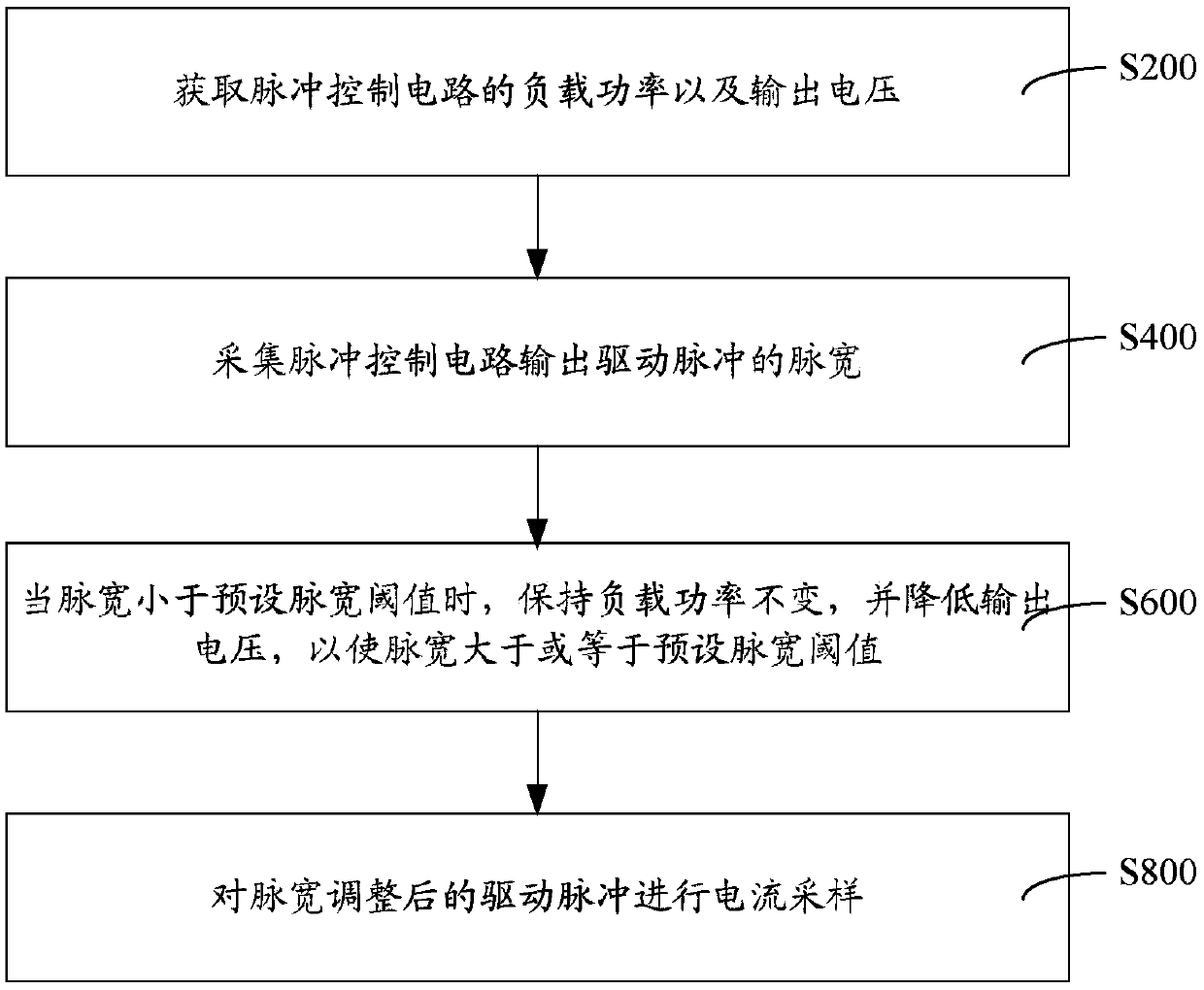
[0044] When the pulse width M is less than the preset pulse width threshold M 阈值 , keep the load power P unchanged, adjust the output voltage for the first time, reduce U by A, and collect the pulse width as M1. When M1 is greater than or equal to M 阈值 , stop reducing the output voltage, that is, the output voltage is U-A at this time; when M1 is still less than M 阈值 , the second output voltage adjustment is performed, and the output voltage is lowered from U-A to B (B is greater than A). At this time, the pulse width is M2. When M2 is greater than or equal to M 阈值 , stop reducing the output voltage, that is, the output voltage is U-A-B at this time; when M1 is still less than M 阈值 , carry out the next output voltage adjustment until MN is greater than or equal to M after the Nth adjustment 阈值 .

[0045] In one embodiment, when the pulse width is less than the preset pulse width threshold, the step of keeping the load power constant and reducing the output voltage so that t...

Embodiment 2

[0053] When the pulse width M is less than the preset pulse width threshold M 阈值 , keep the load power P unchanged, adjust the output voltage for the first time, reduce U by A, and collect the pulse width as M1. When M1 is greater than or equal to M 阈值 , stop reducing the output voltage, that is, the output voltage is U-A at this time; when M1 is still less than M 阈值 , adjust the output voltage for the second time, and reduce the output voltage from U-A to A again. At this time, the pulse width is M2. When M2 is greater than or equal to M 阈值 , stop reducing the output voltage, that is, the output voltage is U-2A at this time; when M1 is still less than M 阈值 , carry out the next output voltage adjustment until MN is greater than or equal to M after the Nth adjustment 阈值 , the output voltage is U-NA after the Nth adjustment.

[0054] Such as Figure 4 As shown, a system for improving the accuracy of current sampling is used to improve the accuracy of current sampling in puls...


PUM


Abstract

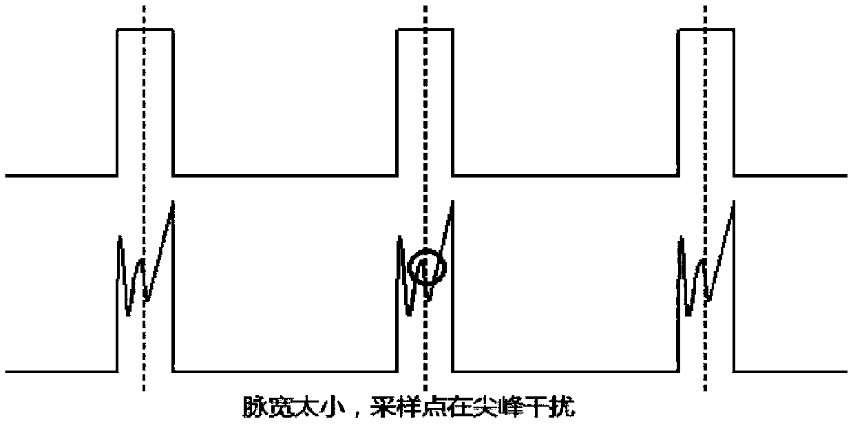
The present invention provides a method and system for improving the accuracy of current sampling, obtain the load power and output voltage of the pulse control circuit, and collect the pulse width of the output driving pulse of the pulse control circuit, when the pulse width is less than the preset pulse width When the threshold value is reached, the load power is kept constant, and the output voltage is reduced so that the pulse width is greater than or equal to the preset pulse width threshold, and the current sampling is performed on the driving pulse after the pulse width is adjusted. During the whole process, under the premise of ensuring that the load power of the pulse control circuit remains unchanged, reduce the output voltage, thereby increasing the pulse width of the pulse control circuit, and avoid the current sampling point at the peak interference point or a similar position due to too small pulse width. The phenomenon of inaccurate current sampling occurs, so that the accuracy of current sampling in the pulse control circuit can be significantly improved.

Description

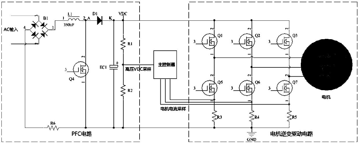
technical field [0001] The invention relates to the technical field of current sampling, in particular to a method and system for improving the accuracy of current sampling. Background technique [0002] In the fields of equipment automation control and adaptive adjustment, current sampling is usually required, and then feedback / adaptive adjustment is performed on the equipment based on the current sampling data. Therefore, if the current sampling is inaccurate, the device will not be able to achieve feedback regulation normally, which will affect the normal operation of the device. [0003] Taking the motor drive and control of the outdoor unit of the inverter air conditioner as an example, the main circuit core framework in the motor drive and control of the outdoor unit of the inverter air conditioner is the power factor correction and the variable frequency drive of the motor (compressor). Among them, PFC (PowerFactor Correction, The power factor correction) circuit mai...

Claims


Application Information

Patent Timeline
Patent Type & Authority Patents(China)
IPC IPC(8): H02M1/00
CPCH02M1/00H02M1/0009
Inventor 尹波
Owner GUANGZHOU SHIYUAN ELECTRONICS CO LTD
Learn More