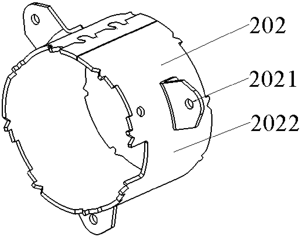
An automatic laser welding device for fixing feet of a motor housing
A technology of laser welding and motor housing, which is applied in laser welding equipment, welding equipment, metal processing equipment, etc., can solve the problems of the maximum bearing capacity limitation of fixed feet, the inability to guarantee the quality of the motor housing, and high production costs. Realize the effect of welding cost and welding quality, make up for the problem of limited bearing capacity, and improve the maximum bearing capacity
- Summary
- Abstract
- Description
- Claims
- Application Information
AI Technical Summary
Problems solved by technology
Method used
Image

Examples
Embodiment Construction
[0029] The present invention will be described in further detail below in conjunction with the accompanying drawings and specific embodiments.
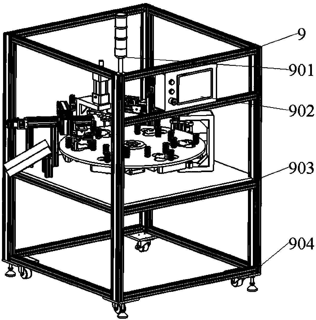
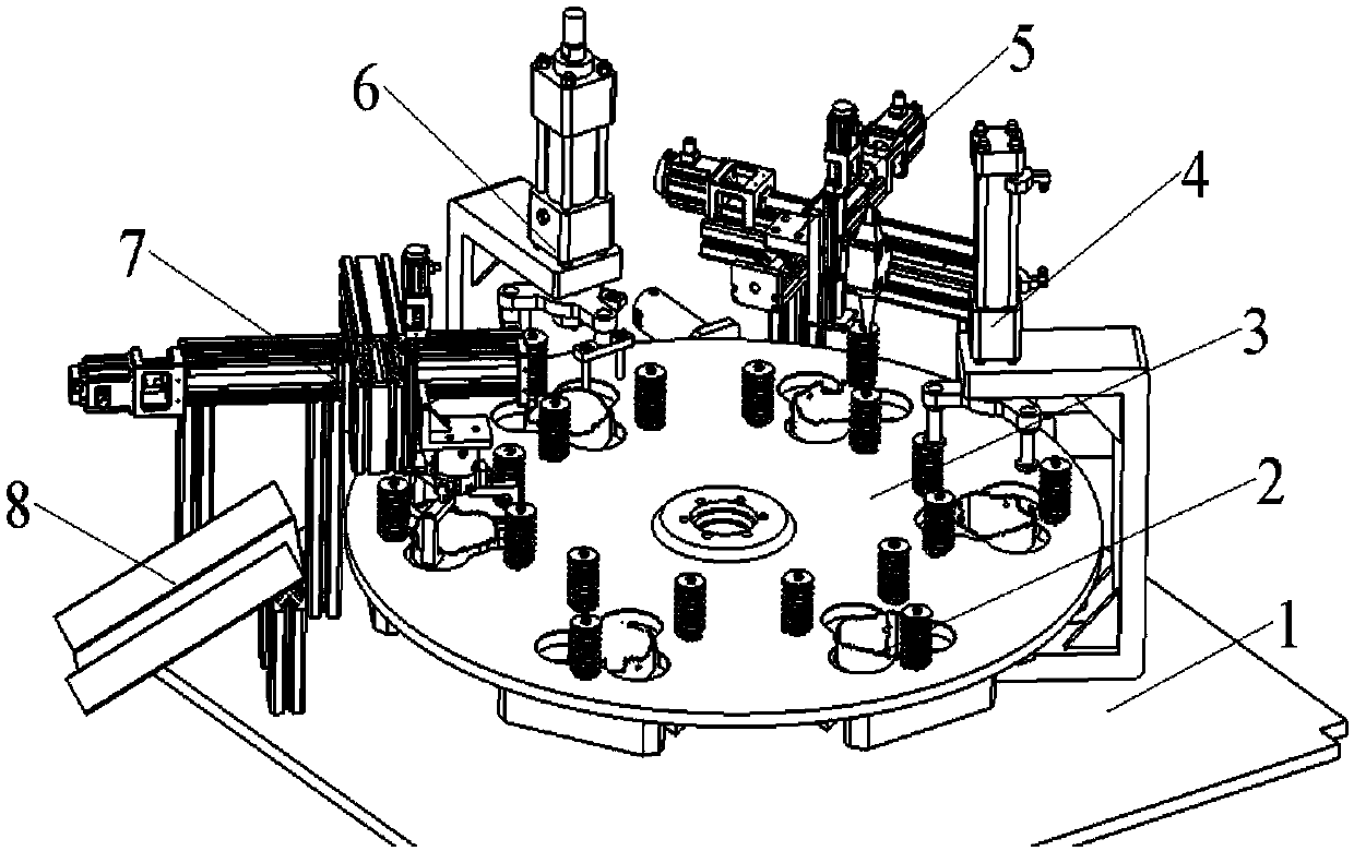
[0030] Such as Figure 1-9 As shown, the present invention provides an automatic laser welding device for the fixed feet of the motor housing. Its main body is driven by a six-degree precision divider. The positions are equipped with the same positioning mold; the periphery of the cam divider worktable is equipped with 5 stations in sequence, which are manual loading station, hydraulic cylinder heavy pressure station, laser resistance composite welding station, and workpiece ejection station. Work station and automatic unloading station.
[0031] The specific structure of the automatic laser welding device for the fixed foot of the motor housing includes a frame 9, a base plate 1, a positioning mold assembly 2, and a cam divider assembly 3 installed on the base plate 1, a hydraulic cylinder heavy pressure assembly 4, a composite Wel...
PUM
 Abstract
Description
Claims
Application Information