Welding table for welding device

A technology of welding device and welding table, which is applied in the direction of auxiliary equipment, welding equipment, auxiliary welding equipment, etc., can solve the problems of inability to fix workpieces in all directions, low welding efficiency, and low degree of freedom of welding workbench mechanism, so as to save physical strength and time , large degree of freedom, and the effect of improving efficiency

Active Publication Date: 2017-02-01
SHAANXI UNIV OF TECH
View PDF9 Cites 7 Cited by
  • Summary
  • Abstract
  • Description
  • Claims
  • Application Information

AI Technical Summary

Problems solved by technology

[0005] The purpose of the present invention is to provide a welding table of a welding device, which solves the problems of low degree of freedom of the mechanism of the existing welding table, inability to fix the workpiece in all directions and low welding efficiency

Method used


Image

  • Welding table for welding device
  • Welding table for welding device

Examples


Embodiment Construction

[0025] The present invention will be described in detail below in conjunction with the accompanying drawings and specific embodiments.

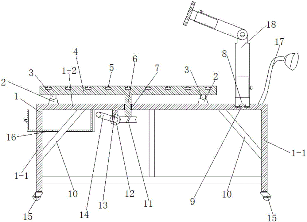
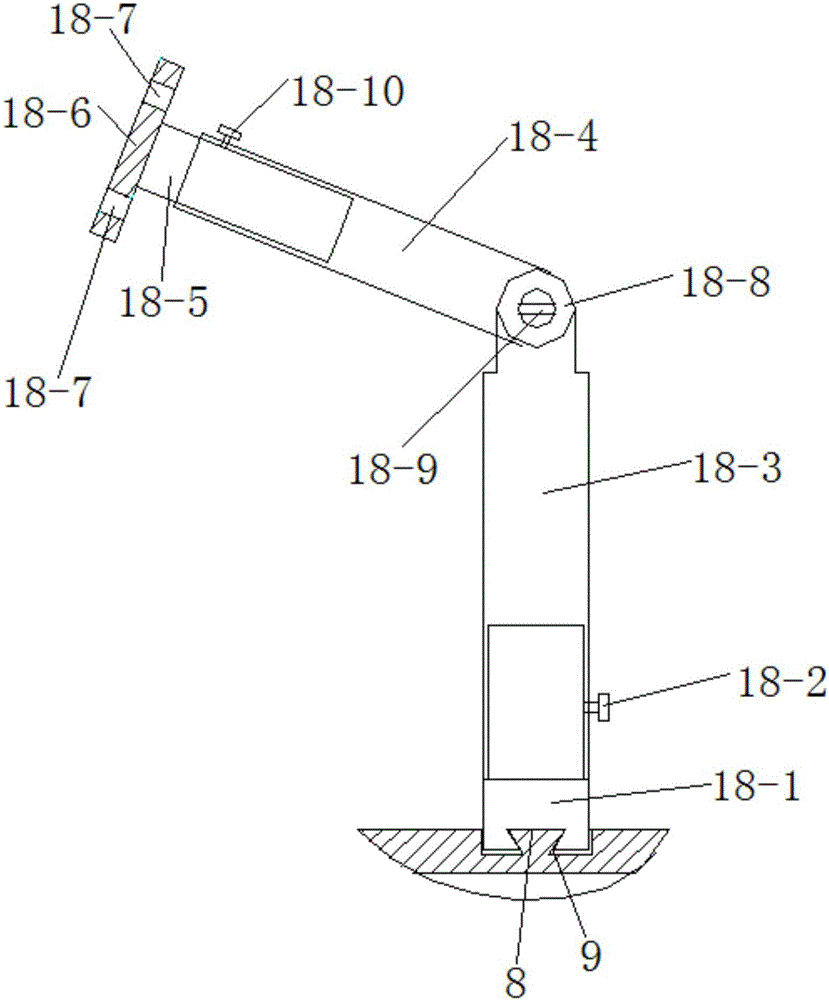
[0026] A welding station of a welding device of the present invention has a structure such as figure 1 As shown, the support frame body 1 is included, the top of the support frame body 1 is provided with a rotary table 4, the bottom of the support frame body 1 is provided with a worm 12, the worm screw 12 meshes with the worm wheel 11, and the worm wheel 11 passes through the rotating shaft 6 and the bottom of the rotary table 4 One end of the worm 12 is connected with a crank handle 14, and one end of the supporting frame body 1 is also provided with a rotating arm clamping mechanism 18.

[0027] At least two inverted T-shaped slots 5 are opened on the rotary table 4 , and the inverted T-shaped slots 5 are parallel to each other and evenly distributed on the rotary table 4 .

[0028] Wherein the support frame body 1 comprises a horizontal s...


PUM


Abstract

The invention discloses a welding table for a welding device. The welding table comprises a supporting frame body; a turn table is arranged above the supporting frame body; a worm is arranged under the supporting frame body and is engaged with a worm wheel; the worm wheel is connected with the bottom of the turn table through a rotary shaft; a crank handle is connected to one end of the worm; and a rotary arm clamping mechanism is further arranged at one end of the supporting frame body. The problems that existing welding workbench mechanisms are low in freedom degree and cannot conduct omnibearing fixing on workpieces are solved.

Description

technical field [0001] The invention belongs to the technical field of mechanical processing and welding, and relates to a welding table of a welding device. Background technique [0002] The welding workbench is a workbench that clamps and fixes the workpiece to facilitate workers to weld. In the existing welding workbench, when performing welding operations on large workpieces, it is often necessary to perform welding operations on multiple parts of the workpieces. Existing welding equipment can only allow workers to perform welding operations by changing working positions around a fixed workpiece. Such a welding process has potential safety hazards, increases the labor intensity of workers, and reduces welding work efficiency. And it is often impossible to weld workpieces with complex positioning positions. [0003] Chinese patent (patent number: ZL201520033673.7, patent name: a rotary welding workbench, publication number: 204524683, publication date: 2015.08.05) discl...

Claims


Application Information

Patent Timeline
Patent Type & Authority Applications(China)
IPC IPC(8): B23K37/04
CPCB23K37/0461
Inventor 张会张昌明顾军陈永平余少军贺洋洋郭昌盛
Owner SHAANXI UNIV OF TECH
Why Eureka
Try Eureka