Milling machine structure
A kind of milling machine, integrated technology, applied in the direction of milling machine, milling machine equipment, milling machine equipment details, etc., can solve the problems such as difficult to ensure the purification effect of cutting fluid, high power consumption, large torque and power consumption, etc., to achieve multiple cycles The effect of using
- Summary
- Abstract
- Description
- Claims
- Application Information
AI Technical Summary
Problems solved by technology
Method used
Image
Examples
Embodiment 1
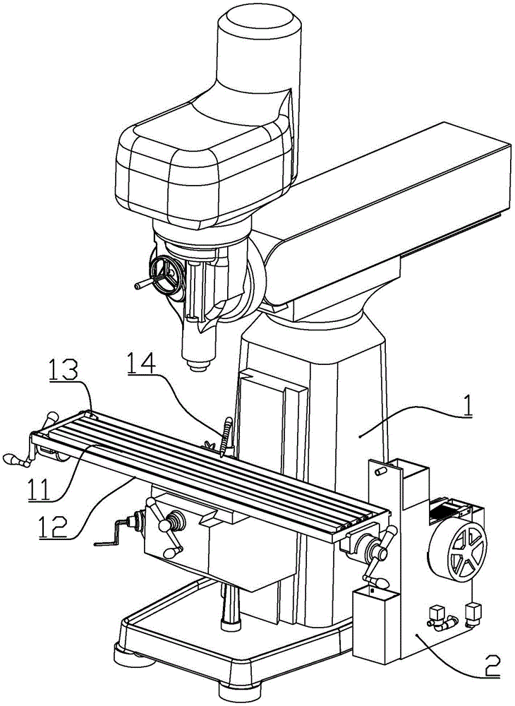
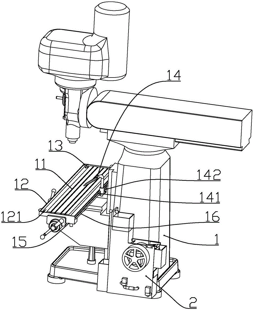
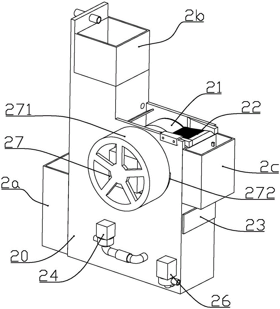
[0076] according to Figure 1 to Figure 19 As shown, a milling machine structure described in this embodiment includes a workbench 11 installed on the main body of the milling machine 1, a collection tray 12 fixedly connected under the workbench, and two horizontal nozzles 13 fixedly installed at one end of the collection tray. And the flushing spray head 14 that is slidably installed on the collecting tray, and the cutting fluid purification device 2 connected with the horizontal spray head and the flushing spray head through pipelines.
[0077] The main body of the milling machine is a conventional milling machine structure, which will not be described here.
[0078] A channel 121 for accommodating cutting fluid is formed between the inner wall of the collecting tray and the outer periphery of the worktable, and a collecting box 15 is connected below a top position of the collecting box; The oily cutting fluid is flushed into the collection box.
[0079] The outer wall of ...
Embodiment 2
[0116] combine Figure 20 to Figure 23 As shown, the present embodiment further makes the following improvements on the basis of embodiment 1:
[0117] The liquid return pump includes a pump body 261, a rotor assembly 262, and a pump cover 263; one end of the pump body is integrally connected with a circular pump cavity 2612, and a cylindrical cavity communicating with the pump cavity is formed in the pump body. The inner diameter of the rotor cavity 2614 is smaller than the inner diameter of the pump cavity, and the bottom of the rotor cavity is fixedly connected with a rotor fixing shaft 2615 coaxially arranged with the rotor cavity.
[0118] A water outlet connector 2613 is formed on the side of the pump cavity; the pump cover is fixedly connected to the outer end of the pump cavity, and a water inlet connector is formed on the pump cover.
[0119]The rotor assembly is installed in the space between the pump body and the pump cover; the rotor assembly includes a magnet rot...
Embodiment 3
[0125] This embodiment further makes the following improvements on the basis of embodiment 1 or 2:
[0126] The filter cotton includes three layers stacked from top to bottom and connected together, the thickness of the top layer is 5mm, the thickness of the middle layer is 8-12mm, and the thickness of the bottom layer is 15-18mm;
[0127] Each layer of filter cotton is composed of a hydrophilic and lipophilic additive layer and a filter layer that wraps the additive layer; the hydrophilic and lipophilic additive layer is made of super amphiphilic material, and the filter layer is composed of a composite filter made of cotton;
[0128] The super amphiphilic material is a nanoscale composite material, which contains a nanoscale space composed of regularly arranged hydrophilic polymer segments and lipophilic polymer segments; the composite material is a sparse porous structure, According to the order from top to bottom, the pore size of the composite material in each layer of f...
PUM
 Abstract
Description
Claims
Application Information
 - R&D
- Intellectual Property
- Life Sciences
- Materials
- Tech Scout
- Unparalleled Data Quality
- Higher Quality Content
- 60% Fewer Hallucinations
Browse by: Latest US Patents, China's latest patents, Technical Efficacy Thesaurus, Application Domain, Technology Topic, Popular Technical Reports.
© 2025 PatSnap. All rights reserved.Legal|Privacy policy|Modern Slavery Act Transparency Statement|Sitemap|About US| Contact US: help@patsnap.com


