Mask plate and display panel production method

A mask and substrate technology, applied in the direction of ion implantation plating, coating, electrical components, etc., can solve local unevenness, seriousness, color mixing and other problems, and achieve the effect of reducing color mixing problems

Active Publication Date: 2017-02-01
EVERDISPLAY OPTRONICS (SHANGHAI) CO LTD
View PDF10 Cites 7 Cited by
  • Summary
  • Abstract
  • Description
  • Claims
  • Application Information

AI Technical Summary

Problems solved by technology

Specifically, it is mainly due to the fact that after the mask template is stretched, it is not completely parallel to the substrate or there is local unevenness, which causes the organic material to deviate from the original position and diffuse laterally into the adjacent pixel area during evaporation. , resulting in color mixing
And as the resolution of display panel products increases, the problem of color mixing will become increasingly serious

Method used


Image

  • Mask plate and display panel production method
  • Mask plate and display panel production method
  • Mask plate and display panel production method

Examples


no. 1 example

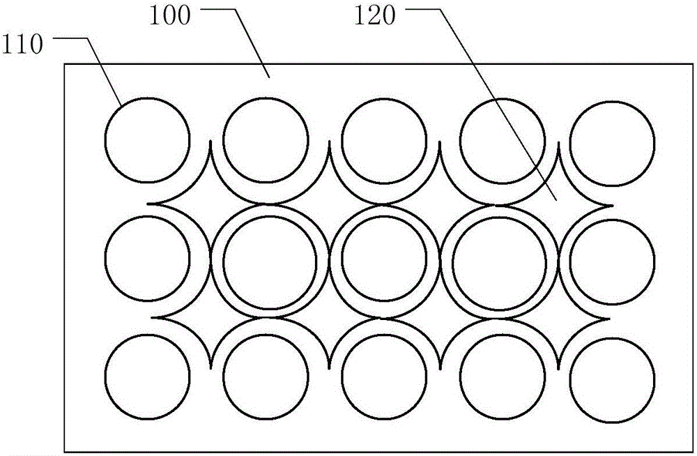
[0036] In order to avoid pixel color mixing, the present invention provides a mask plate used in the evaporation process of the display panel. Preferably, the mask is a metal mask. refer to figure 1 , which shows a schematic diagram of the mask plate of the present invention. The mask plate includes a body 100 having a plurality of openings 110 and a spacer. The opening 110 defines a thin film pattern, such as a pixel pattern. The opening 110 may be in the shape of a circle, a rectangle, a rhombus, a trapezoid or other irregular shapes, so that the pattern of the thin film evaporated using the mask is also a circle, a rectangle, a rhombus, a trapezoid or other irregular shapes. A plurality of openings 110 are arranged along the row direction and the column direction to form an array of openings to form a pixel array in the evaporation process of the display panel. The spacer is located between adjacent openings 110 . A plurality of spacers 120 are provided on the spacer. ...

no. 2 example

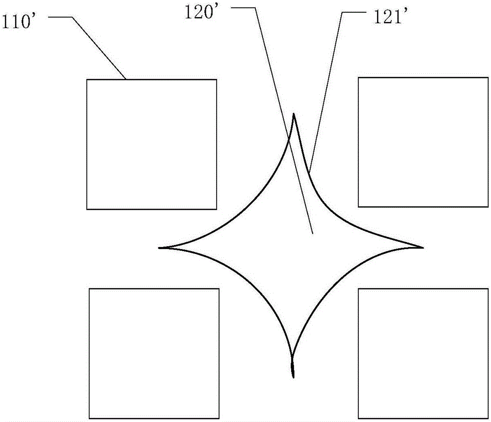
[0040] see Figure 2B ,and Figure 2A Similarly, each spacer 120' is located between four adjacent openings 110'. The edge of each spacer 120' facing the opening 110' adjacent thereto does not have a shape suitable for the opening 110'. For example, each opening 110' is rectangular, and the spacer 120' between the four rectangular openings 110' has four arc-shaped edges 121' respectively facing the four rectangular openings 110'. Preferably, each arc-shaped edge 121' has the same center as the rectangular opening 110' facing it.

no. 3 example

[0042] see Figure 2C ,and Figure 2B Similarly, each spacer 120" is located between four adjacent openings 110". The edge of each spacer 120" facing the opening 110" adjacent to it has a shape suitable for the opening 110". For example, each opening 110" is a rectangle, and the interval between four rectangular openings 110" The piece 120" has fold-line-shaped edges 122" respectively facing the four rectangular openings 110". Preferably, each zigzag edge 122" has two sides parallel to the length and width of the rectangular opening 110', respectively. Each zigzag edge 122" has the same center as the rectangular opening 110' facing it.

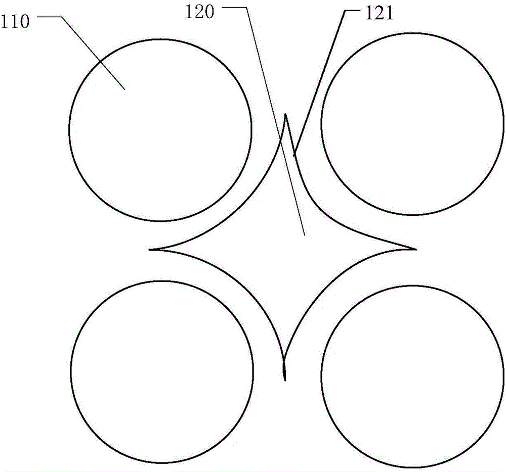
[0043] Specifically, the above Figure 2A The first embodiment shown, Figure 2B The second embodiment shown and Figure 2C In the third embodiment shown, the four spacers adjacent to an opening are engaged such that the opening is located within the closed area formed by the four spacers adjacent thereto.


PUM


Abstract

The present invention provides a mask plate and a display panel production method. The mask plate comprises: a body, wherein the body is provided with a plurality of opening parts and interval regions, the opening part defines a pixel pattern, and the interval regions are positioned between the adjacent opening parts; and interval members arranged on the interval regions of the body. With the mask plate and the display panel production method of the present invention, the pixel color mixing problem can be solved.

Description

technical field [0001] The invention relates to the field of display technology, in particular to a method for manufacturing a mask plate and a display panel. Background technique [0002] In recent years, OLED (Organic Light-Emitting Diode, Organic Light-Emitting Diode) technology has developed rapidly, and has become a promising technology most likely to replace LCD (Liquid Crystal Display, Liquid Crystal Display). [0003] In the OLED substrate manufacturing process, the various layers in the organic light emitting element are usually formed by evaporation process. That is to say, the thin film pattern corresponding to the pixel is usually formed on the substrate by using a mask plate having openings corresponding to the thin film pattern to be formed. In order to form openings corresponding to fine film patterns, the thickness of the mask plate is usually very thin, and the interval between the openings is very small. When handling such a mask plate, it is easy to bend ...

Claims


Application Information

Patent Timeline
Patent Type & Authority Applications(China)
IPC IPC(8): C23C14/04
CPCC23C14/042B05B12/20H10K59/12H10K71/166
Inventor 黄俊杰
Owner EVERDISPLAY OPTRONICS (SHANGHAI) CO LTD
Why Eureka
Try Eureka