
Image reading method and image reading apparatus

Inactive Publication Date: 2006-03-21
FUJIFILM CORP
View PDF9 Cites 7 Cited by
  • Summary
  • Abstract
  • Description
  • Claims
  • Application Information

AI Technical Summary

Benefits of technology

[0017]An object, therefore, of the present invention is to solve the above-mentioned prior art problems and to provide an image reading method in which a light quantity balance of a sensor system composing a scanner (image sensor) is adjusted in accordance with a film type to be used as the original so as to be capable of high-precision image reading without creating a problem that a muddy color is generated, and an image reading apparatus adopting the method.
[0026]It is also preferable that the light quantity balance adjusting means changes the optical balance in the optical system from the light source to the image sensor including said original and decreases color mixing in the three primary colors.
[0033]Moreover, in the image reading method and the image reading apparatus according to the invention, the color negative film and the color reversal film which have spectral density distributions as shown in FIGS. 9 and 10 can be changed so as to have spectral density distributions as shown in FIGS. 11 and 12 by using a notch filter in addition to the light quantity balance adjusting filter. By this, in reading the color negative film and the color reversal film, it is capable of making roughly uniform the wavelength corresponding to the peak value of the spectral density distribution for each color, thereby allowing the later image processing to be efficiently performed.

Problems solved by technology

Here, a problem lies in that a big difference in color balance (light quantity balance) of the image information read by the scanner (image sensor) exists between the color negative film and the color reversal film.
However, since a base density of the color negative film greatly differs from that of the color reversal film, a problem is created when the color negative film is read in that the color balance (light quantity balance) of image information of the color negative film read by the scanner (image sensor) greatly differs from that of the color reversal film.
This problem is generated only when a so-called three-color simultaneous reading is performed and is not generated when three colors are separately read in order.
In such characteristics, the image sensor has a cross talk (tailing portion of long wavelength side B in FIG. 7) of spectral sensitivity; hence, a new problem which causes a remarkably muddy color is generated.
Same with the case that the color balances (light quantity balance) of respective image information are different from each other, the above big difference will cause another problem that a completely different reading condition such as the light quantity balance including a light source or the like is necessary to be separately set depending on whether an image on the color reversal is read or an image on the color negative films is read.

Method used


Image

  • Image reading method and image reading apparatus
  • Image reading method and image reading apparatus
  • Image reading method and image reading apparatus

Examples


Embodiment Construction

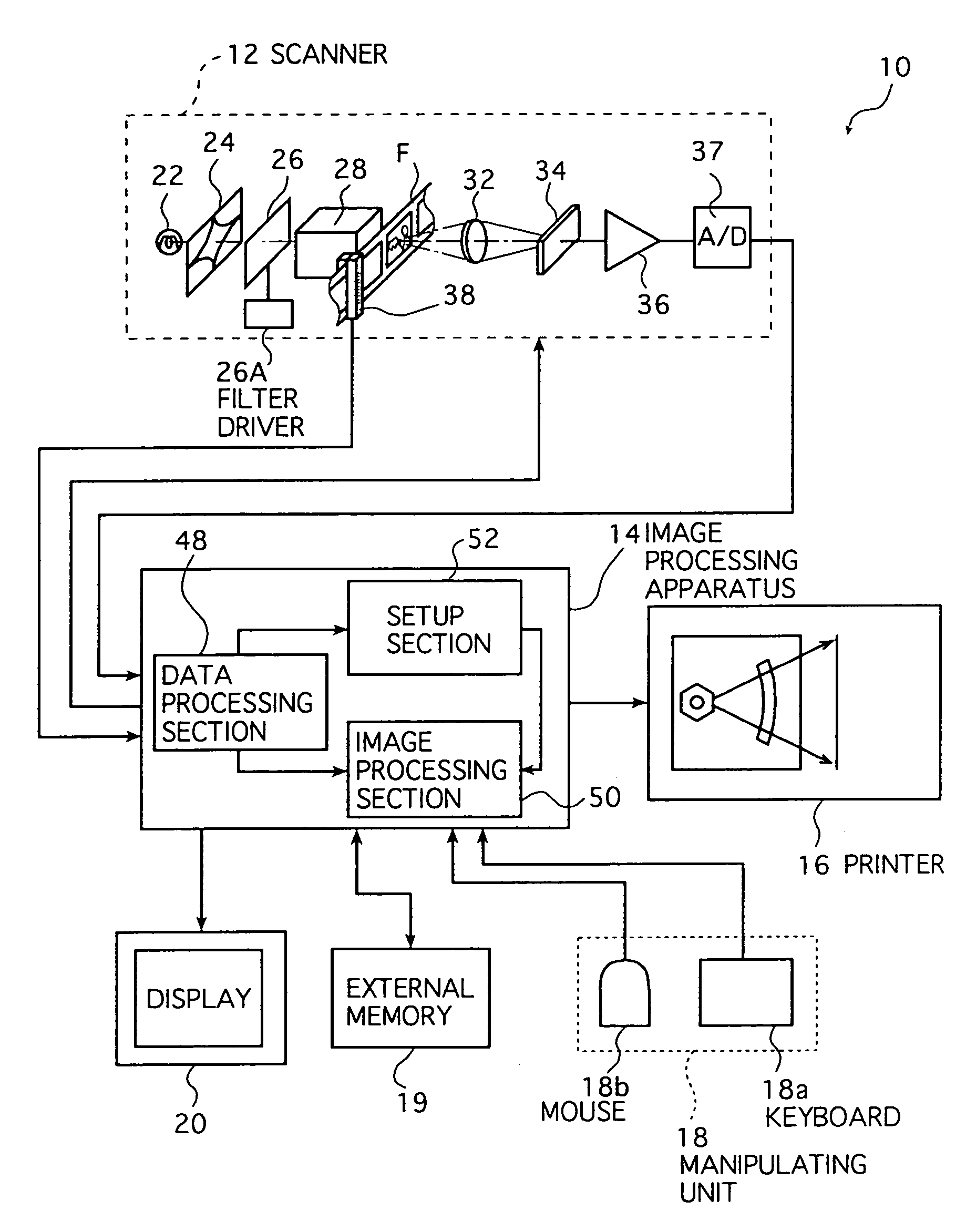
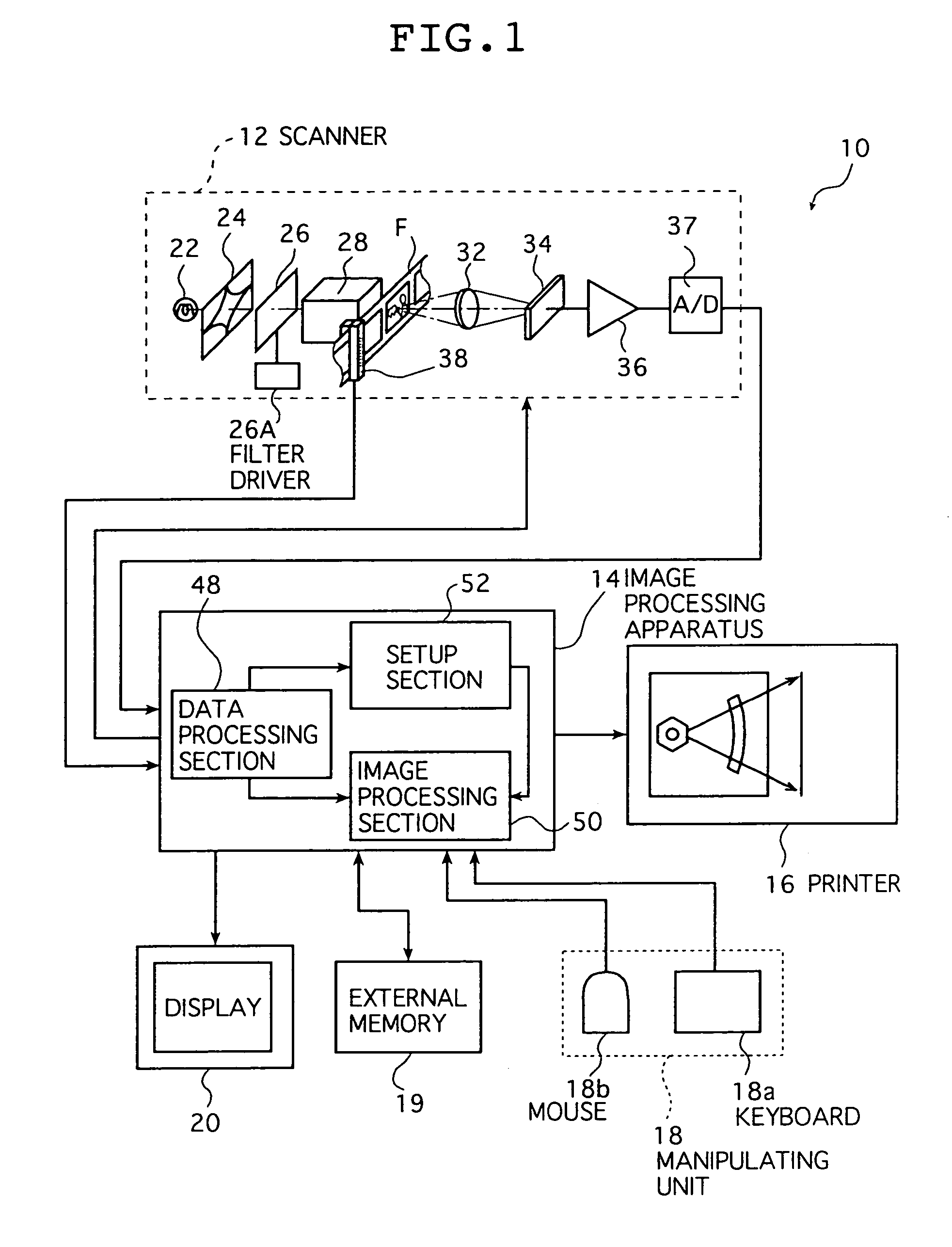
[0051]The image reading method and the image reading apparatus of the invention are now described in detail below with reference to the preferred embodiments shown in the accompanying drawings.

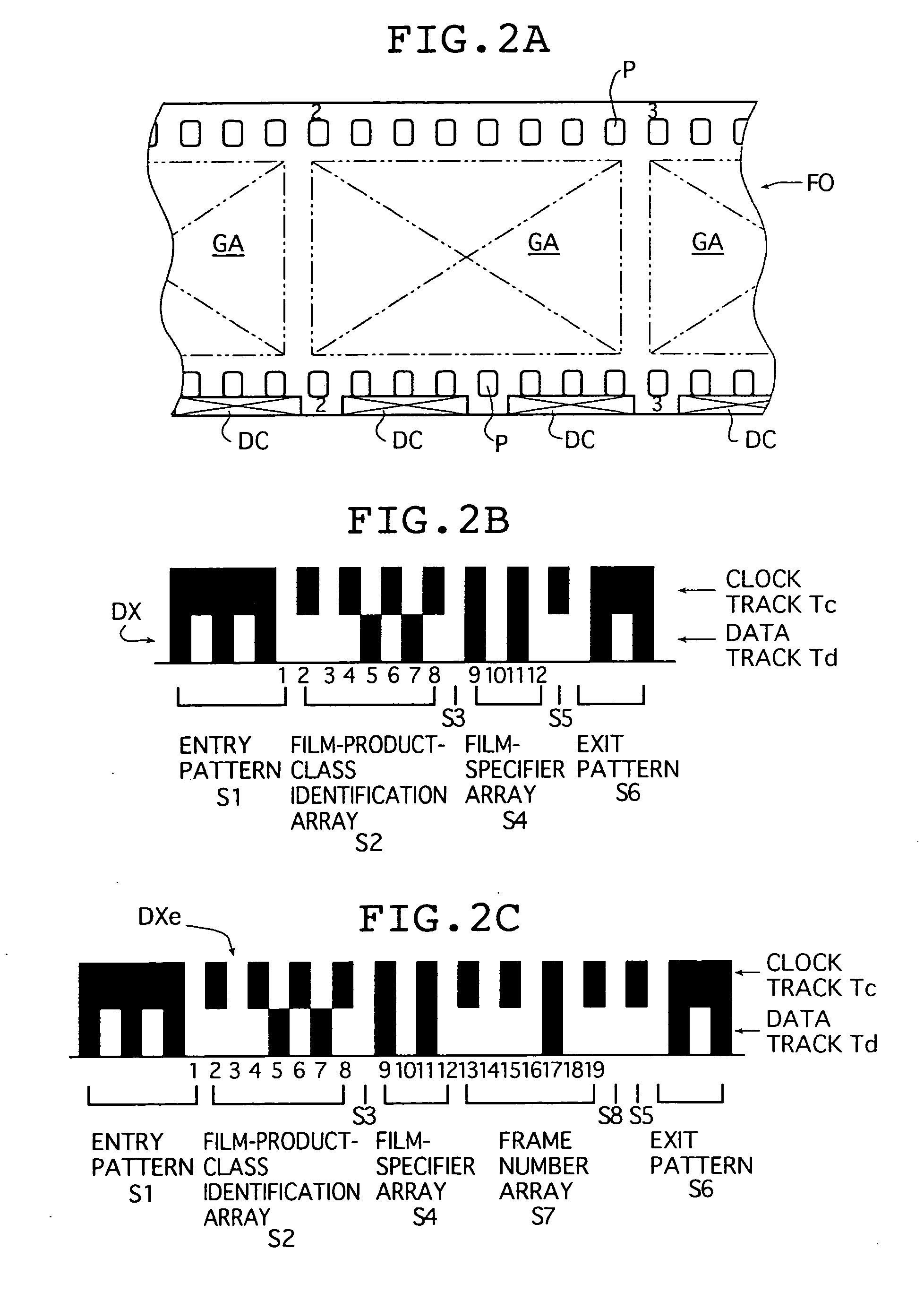
[0052]First, a DX code and an expanded DX code which are used for identifying a film type in a color digital printer according to an embodiment as described below will now be described.

[0053]FIG. 2A is a schematic view showing a recording position DC of a DX code DX or an expanded DX code DXe of 135 negative film; FIGS. 2B and 2C illustrate examples of two codes, that is, a DX code DX and an expanded DX code Dxe, respectively.

[0054]As shown in FIG. 2A, when a negative film F0 of 135 size is placed with the emulsion coated side down and the frame number increasing from left to right of the figure, the DX code DX or the expanded DX code DXe is recorded in two portions for an image region GA of each frame with an ordinary full size at the bottom edge in the figure, that is, in the bottom edge reg...


PUM


Abstract

There is provided an image reading method, comprising the steps of reading photoelectrically an original image with an image sensor by separating it into three primary colors and converting image signals of the three primary colors outputted from the image sensor into digital signals, wherein light quantity of light which is incident on the image sensor is balanced with every color in accordance with an original type. When the image is photoelectrically read, the high-precision image reading can be attained without creating a muddy color. Moreover, the image reading conditions need not be changed, even when the film types are changed.

Description

BACKGROUND OF THE INVENTION[0001]The present invention relates to the technical field of a method and an apparatus for photoelectrically reading original images, particularly images recorded on photographic films.[0002]At present, most of the images recorded on photographic films such as negatives and reversals (which are hereinafter referred to simply as “films”) are printed onto light-sensitive materials (photographic papers) by a technique generally called “direct exposure (analog exposure) in which the light-sensitive materials are exposed with the light protected from the films.[0003]On the other hand, a printer which adopts a technique generally called “digital exposure”, that is, a color digital printer, has recently been commercialized. In this “color digital printer”, the image recorded on a film is read photoelectrically and converted into digital signals which are subjected to various kinds of image processing to produce recording image data; a light-sensitive material is...

Claims


Application Information

Patent Timeline
IPC IPC(8): G06F15/00
CPCH04N1/40056H04N1/6094H04N1/486
Inventor YAMAZAKI, YOSHIROU
Owner FUJIFILM CORP
Learn More