Ceiling type detector

A detection device, a ceiling-mounted technology, applied in the field of field detection, can solve the problems of large size, inconvenient to carry, low accuracy, etc., and achieve the effect of high detection efficiency, improved efficiency, and simple operation

Active Publication Date: 2017-02-01
NANJING DASSAULT AVIATION TECH CO LTD
View PDF5 Cites 2 Cited by
  • Summary
  • Abstract
  • Description
  • Claims
  • Application Information

AI Technical Summary

Problems solved by technology

Traditional inspection equipment mainly includes scaffolding, work baskets and bridge inspection vehicles, etc. These equipment are bulky, inconvenient to carry, and the accuracy is not strong

Method used


Image

  • Ceiling type detector
  • Ceiling type detector
  • Ceiling type detector

Examples


Embodiment 1

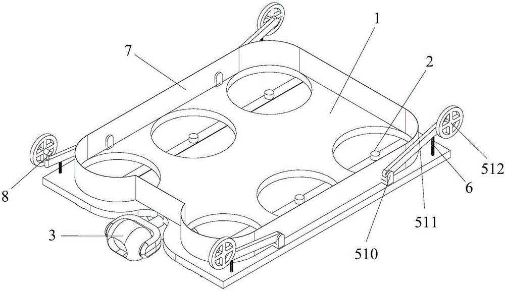
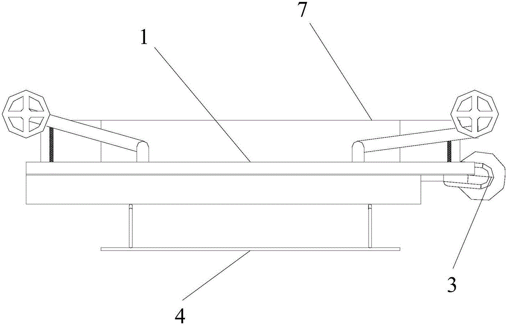
[0032] combine figure 1 with figure 2 , the ceiling-absorbing detection device of the present invention comprises a main body 1, the main body 1 is provided with a lifting device 2, a detector 3, a moving device and a landing gear 4, and the landing gear 4 and the moving device are distributed on two opposite sides of the main body 1 , the lifting device 2 is a propeller structure, the moving device is driven by wheels or crawlers, and the moving device is provided with a shock absorbing mechanism.

[0033] Further, the lifting device 2 is provided with a semi-sealed enclosure ring 7 on the side of the main body 1 where the mobile device is installed. The design of the retaining ring 7 makes it easier to form a negative pressure when the device works on the roof, and the efficiency is higher.

[0034] In this embodiment, the retaining ring 7 is an integral structure, which surrounds the lifting device 2 as a whole.

[0035] In this embodiment, the mobile device is driven b...

Embodiment 2

[0046] combine Figure 4, compared with Embodiment 1, the ceiling-mounted detection device of this embodiment differs in that:

[0047] In this embodiment, the retaining ring 7 is an independent structure, and each propeller is provided with an independent retaining ring 7 .

[0048] The remaining technical features are the same as those of the ceiling-mounted detection device in Embodiment 1, and will not be repeated here.

[0049] Of course, the setting of the retaining ring 7 is not limited to this, for example, according to the number of propellers, one retaining ring 7 is arranged in each column or row.

[0050] Of course, the lifting device 2 of the ceiling-mounted detection device in this embodiment can also adopt the setting of a four-propeller structure, such as Figure 5 shown.

Embodiment 3

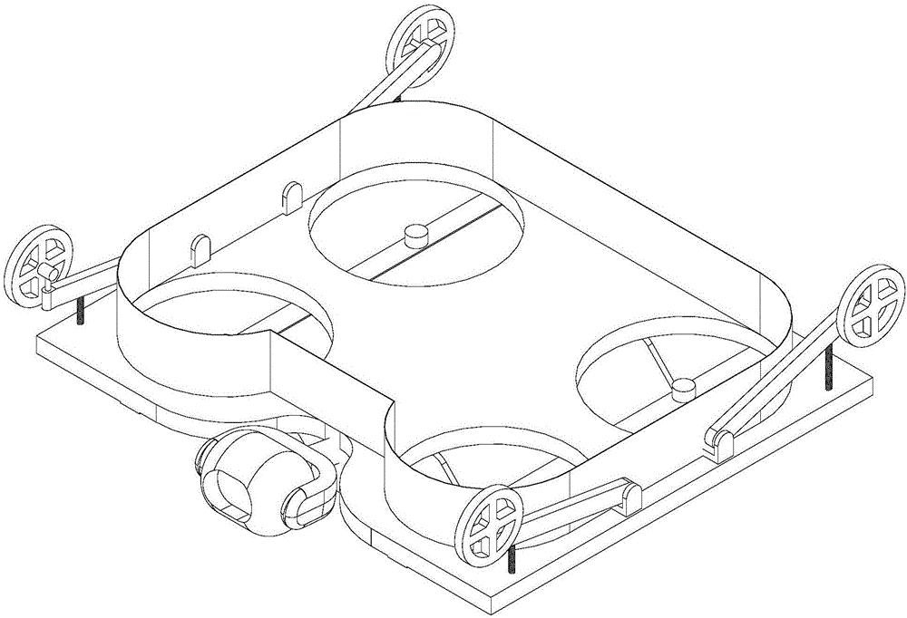
[0052] combine Image 6 , compared with Embodiment 2, the ceiling-mounted detection device of this embodiment differs in that:

[0053] In this embodiment, the mobile device is provided with three groups of wheel frames 511 and wheels 512, wherein two groups of wheel frames 511 and wheels 512 are installed on two corners on one side of the ceiling-mounted detector 3, and the other group of wheel frames 511 and wheels 512 Installed at the midpoint where two groups of wheel frames 511 and wheels 512 are installed side-to-side, such as image 3 shown.

[0054] In this embodiment, the two wheels 512 installed on two corners of one end of the detector 3 are driving wheels, which are driven by a motor, and the other wheel 512 is a driven wheel. In this embodiment, the wheel frame 511 of the driving wheel is provided with a steering mechanism 8, which can facilitate the arbitrary movement of the ceiling-mounted detection device during operation and improve the working efficiency of...


PUM


Abstract

The invention relates to a ceiling type detector. The ceiling type detector comprises a main body provided with a lifting device, a detecting instrument, a moving device and an undercarriage. The undercarriage and the moving device are distributed on the two opposite faces of the main body. The lifting device is of a propeller structure. The moving device is driven by wheels or tracks. The moving device is provided with a damping mechanism. Through the ceiling type detector, the function of detection by entering a working face is achieved, higher stability is achieved during detection, the work range of detection is extended, the detection precision and detection efficiency are improved, and the ceiling type detector has the advantages of being wide in application range, high in detection precision and detection efficiency and easy to operate.

Description

technical field [0001] The invention relates to the technical field of field detection, in particular to a ceiling-mounted detection device. Background technique [0002] With the rapid development of science and technology and transportation, the development speed of the construction industry is also advancing by leaps and bounds. After the building is completed and put into use, regular inspections must be done regularly to ensure traffic safety, people's property and public interests. However, some inspections need to be inspected at the bottom of tall buildings, such as bridges and tunnel lights. The routine inspection of bridges includes the inspection of the substructure of the bridge. Traditional inspection equipment mainly includes scaffolding, work baskets and bridge inspection vehicles, etc. These equipment are bulky, inconvenient to carry, and not very accurate. Contents of the invention [0003] The technical problem to be solved by the present invention is t...

Claims


Application Information

Patent Timeline
Patent Type & Authority Applications(China)
IPC IPC(8): E01D19/10
CPCE01D19/106
Inventor 杨思强汪俊王波蔺靓于传稳
Owner NANJING DASSAULT AVIATION TECH CO LTD
Why Eureka
Try Eureka