Stamping device suitable for machining automobile parts in different sizes

A technology of auto parts and stamping devices, which is applied in the field of stamping machines, can solve the problems of being unable to adapt to different sizes of auto parts, difficult to meet the use needs, and increasing the investment cost of enterprises, so as to improve convenience, reduce investment costs, The effect of improving usability

Active Publication Date: 2019-11-22
永康市戈平工贸有限公司
View PDF15 Cites 8 Cited by
  • Summary
  • Abstract
  • Description
  • Claims
  • Application Information

AI Technical Summary

Problems solved by technology

[0003] Most of the traditional stamping devices for auto parts are used in a small range and cannot be applied to the processing of auto parts of different sizes, so different workpieces need to be used Stamping device, which in turn increases the investment cost of the enterprise, reduces the efficiency of stamping, and is difficult to meet the needs of use. Therefore, we have proposed a stamping device for auto parts that is suitable for processing different sizes to solve the problems raised in the above-mentioned background technology. The problem

Method used


Image

  • Stamping device suitable for machining automobile parts in different sizes
  • Stamping device suitable for machining automobile parts in different sizes
  • Stamping device suitable for machining automobile parts in different sizes

Examples


Embodiment 1

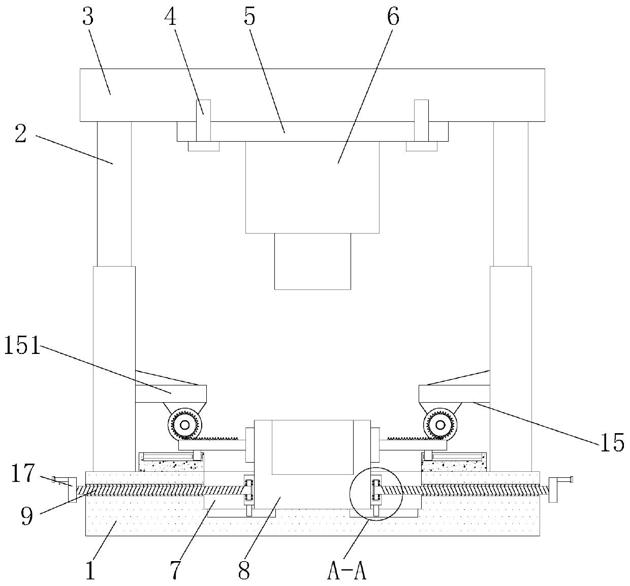
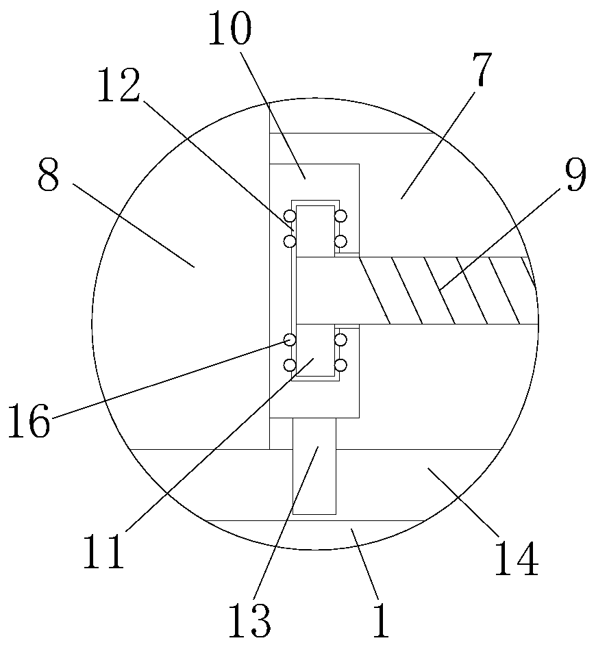
[0022] Example 1: See Figure 1-4 , a stamping device suitable for processing auto parts of different sizes, including a base 1, the left and right sides of the top of the base 1 are fixedly connected with an upper top plate 3 through a telescopic column 2, and the bottom of the upper top plate 3 is threaded through a mounting bolt 4. The upper mold mounting plate 5, the bottom of the upper mold mounting plate 5 is fixedly connected with the upper mold body 6, the top of the base 1 is provided with a lower mold fixing groove 7, and the inside of the lower mold fixing groove 7 is provided with a lower mold body 8, and the base 1 is left and right Threaded rods 9 are provided on both sides and corresponding to the position of the lower mold fixing groove 7. The end of the threaded rod 9 away from the base 1 is fixedly connected with a rocker 17. The end of the threaded rod 9 close to the base 1 runs through the base 1 and the lower mold in turn. The groove 7 extends to the insid...

Embodiment 2

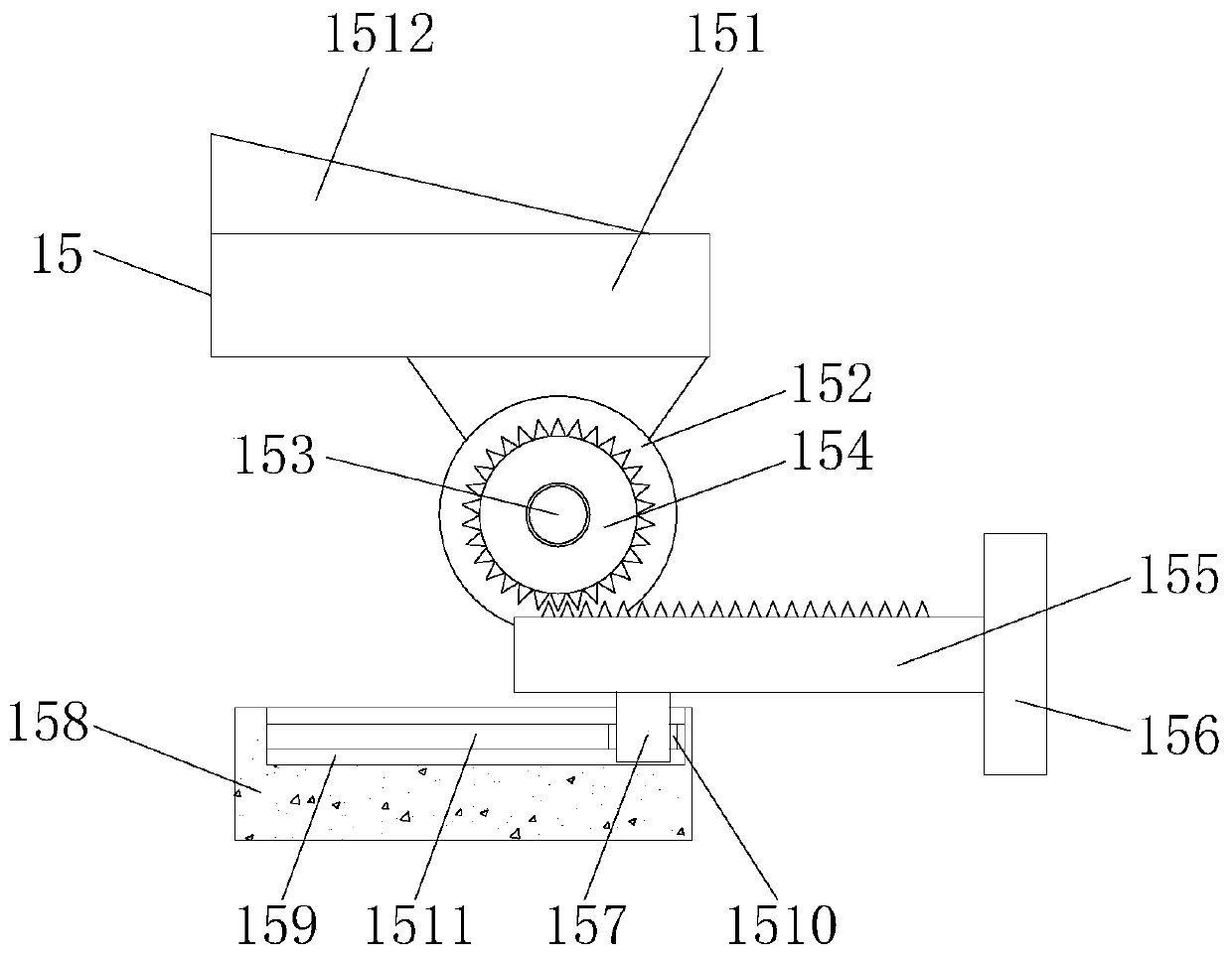
[0025]Embodiment 2: On the basis of the first embodiment, on the right side of each second clamping plate 156 and increase a T-shaped thin strip with a scale, so that the verticality of the lower mold when it is clamped and the lower mold and The centering or fixed-distance placement of the upper mold is specifically designed to be provided with a T-shaped thin strip on the side away from the rack 155 on the second clamping plate 156. The T-shaped thin strip includes a straight line segment and two perpendicular to the straight line segment. Horizontal section, one end of the straight section is connected to the intersection point of the two horizontal sections, scales are provided on the straight section and the two horizontal sections and both can be stretched, the ends of the two horizontal sections and the ends of the two horizontal sections The front end on the handover point is provided with a magnet, and the specific working process of this embodiment is as follows: when...


PUM


Abstract

The invention discloses a stamping device suitable for machining automobile parts in different sizes. The stamping device comprises a base, wherein the left side and the right side of the top of the base are fixedly connected with an upper top plate through telescopic columns; the bottom of the upper top plate is in threaded connection with an upper mold mounting plate through a mounting bolt; anupper mold body is fixedly connected to the bottom of the upper mold mounting plate; a lower mold fixing groove is formed in the top of the base; a lower mold body is arranged inside the lower mold fixing groove; and threaded rods are arranged on the left side and the right side, corresponding to the positions of the lower mold fixing grooves, of the base. The stamping device is reasonable in structural design, convenient to use, and applicable to machining the automobile parts with different sizes without using different stamping devices for machining, so that the practicability of the deviceis greatly improved, the investment cost of enterprises is reduced, the stamping efficiency is improved, and the use requirements in all directions are met.

Description

technical field [0001] The invention relates to the technical field of stamping machines, in particular to a stamping device for auto parts suitable for processing different sizes. Background technique [0002] The punching machine drives the flywheel through the motor, and through the clutch, the transmission gear drives the crank linkage mechanism to move the slider up and down, and drives the drawing die to form the steel plate. The so-called double action means that the press has two sliders, which are divided into an inner slider and an outer slider. The inner slider drives the punch or die of the mold, and the outer slider drives the blankholder on the mold. When the blank holder first moves to press the edge of the steel plate, the inner slider moves again to stretch. [0003] Most of the traditional stamping devices for auto parts are used in a small range and cannot be applied to the processing of auto parts of different sizes. Therefore, different stamping devices...

Claims


Application Information

Patent Timeline
Patent Type & Authority Applications(China)
IPC IPC(8): B21D37/14B21D37/12B21D53/88
CPCB21D37/14B21D37/12B21D53/88
Inventor 张鑫忠
Owner 永康市戈平工贸有限公司
Why Eureka
Try Eureka