A piezoelectric deceleration belt energy recovery device

A technology of energy recovery device and speed bump, which is applied in the direction of piezoelectric effect/electrostriction or magnetostriction motor, electrical components, generator/motor, etc. and other issues, to achieve the effect of high recovery ratio, comprehensive energy recovery and convenient installation

Active Publication Date: 2018-08-21
邳州泰利恒商贸有限公司
View PDF12 Cites 0 Cited by
  • Summary
  • Abstract
  • Description
  • Claims
  • Application Information

AI Technical Summary

Problems solved by technology

This also makes the existing speed bump power generation device have a common problem, that is, because the speed bump can move up and down when the vehicle passes the speed bump, which reduces the bumpy feeling when the vehicle passes the speed bump, over time, these speed bumps will be It loses its primary function of forced deceleration as a speed bump, and becomes a simple power generation device.
At the same time, when the vehicle passes the deceleration belt, it has to go through four stages: hitting the deceleration belt, climbing, falling back, and hitting the ground. The existing energy recovery device only recovers the energy wasted by the change of the gravitational potential energy of the vehicle, which is limited to the climbing process of the vehicle. It does not consider the energy wasted when the wheel hits the speed bump and hits the ground when it leaves the speed bump, so the energy recovery is not comprehensive enough and the efficiency is low

Method used


Image

  • A piezoelectric deceleration belt energy recovery device
  • A piezoelectric deceleration belt energy recovery device
  • A piezoelectric deceleration belt energy recovery device

Examples


Embodiment Construction

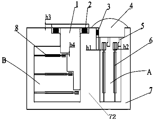
[0017] The present invention will be further described below in conjunction with the accompanying drawings and specific embodiments. It should be understood that the following specific embodiments are only used for the present invention, but are not intended to limit the scope of the present invention. It should be noted that the words "front", "rear", "left", "right", "upper" and "lower" used in the following description refer to the vehicle as the reference, with the direction of the vehicle as the front, relative The direction of the surface is the rear, the ground is the bottom, and the car is above the ground.

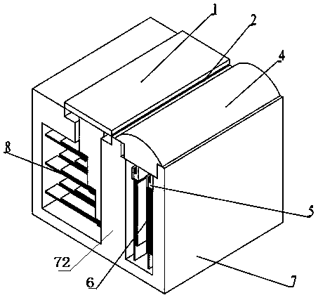
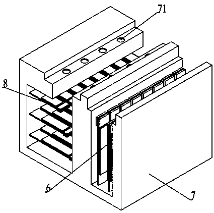
[0018] Such as figure 1 As shown, the outside of the present invention is a box body 7 of cuboid structure, which is installed below the ground as a whole, and the top surface of the box body 7 is flush with the ground. Inside the box body 7, a partition 72 is used to divide the inside of the box body 7 into two parts, the front power generation room B and the re...


PUM


Abstract

The invention discloses a piezoelectric type deceleration strip energy recovery device which can be used for recovering vibration energy generated when a vehicle passes through a deceleration strip. The piezoelectric type deceleration strip energy recovery device is provided with a box which is mounted underground. The interior of the box is partitioned into a front power generation chamber and a rear power generation chamber by a partition plate. A horizontal spring, impacting blocks and vertical cantilever vibrators are arranged in the rear power generation chamber. The deceleration strip is arranged at a stepped opening in the top of the rear power generation chamber. The horizontal spring is mounted between the front side wall of the lower section of the deceleration strip and the inner wall of the front side of the opening in the top of the rear power generation chamber. The lower portion of the deceleration strip is fixedly connected with the impacting blocks. Horizontal cantilever vibrators, a lower pressing plate and vertical springs are arranged in the front power generation chamber. The lower pressing plate is mounted at a stepped opening of the front power generation chamber. The vertical springs are mounted between the upper section of the lower pressing plate and the stepped opening of the front power generation chamber. According to the piezoelectric type deceleration strip energy recovery device, on the premise that the function of the deceleration strip is guaranteed, energy consumed due to changes of gravitational potential energy when the vehicle passes through the deceleration strip can be recovered, and momentum consumed due to collision between vehicle wheels and the deceleration strip can also be recovered.

Description

technical field [0001] The invention belongs to the technical field of vehicles and road traffic, and relates to a deceleration belt placed on a road for forcing vehicles to decelerate, and in particular to a device capable of recovering vibration energy generated when a vehicle passes through the deceleration belt. Background technique [0002] For the sake of driving safety, the road traffic management department has set up speed bumps on important roads such as highway toll stations, community gates, and school gates to force vehicles to slow down and improve the safety of people's travel. When the vehicle passes the deceleration belt, it will experience the process of impact, climbing, descending and falling back to hit the ground. This process wastes a lot of energy. If this part of energy can be recovered and used for nearby traffic lights, street lights and other road supporting facilities Power supply will produce good economic and environmental benefits. [0003] T...

Claims


Application Information

Patent Timeline
Patent Type & Authority Patents(China)
IPC IPC(8): E01F9/529H02N2/18
CPCH02N2/186
Inventor 王乐乐何仁
Owner 邳州泰利恒商贸有限公司
Why Eureka
Try Eureka