Hydrodynamic force conversion device

A conversion device, fluid power technology, applied in the direction of machine/engine, rotary piston engine, rotary or oscillating piston engine, etc., can solve the problems of low energy conversion efficiency, complex structure of gas turbine or water turbine, etc., to achieve simple structure, low cost Low, easy-to-manufacture effect

Active Publication Date: 2017-02-01
唐翊翃
View PDF5 Cites 7 Cited by
  • Summary
  • Abstract
  • Description
  • Claims
  • Application Information

AI Technical Summary

Problems solved by technology

[0003] The purpose of the present invention is to provide a fluid power conversion device, which aims to solve the technical problems that the existing gas turbine or water turbine not only has a complex structure, but also has low energy conversion efficiency

Method used


Image

  • Hydrodynamic force conversion device
  • Hydrodynamic force conversion device
  • Hydrodynamic force conversion device

Examples


no. 1 example

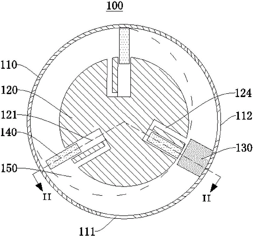
[0034] figure 1 For the schematic structural diagram of the fluid power conversion device provided in this embodiment, please refer to figure 1 .

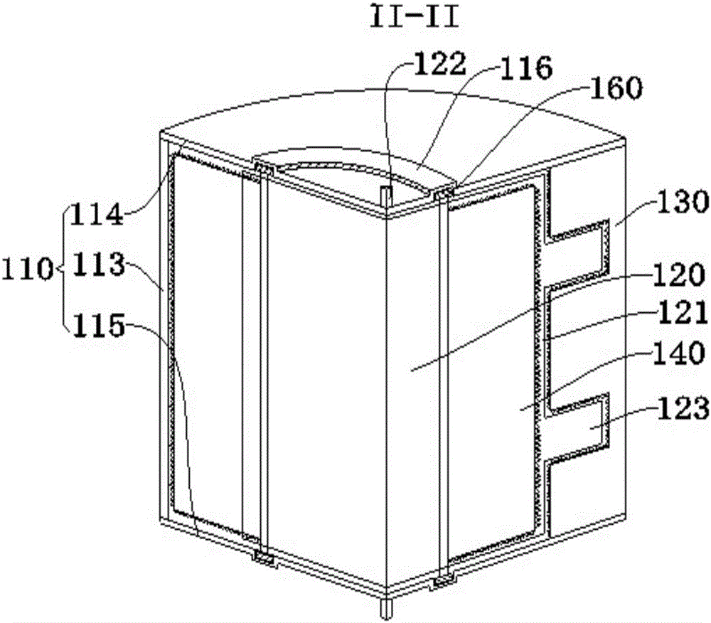
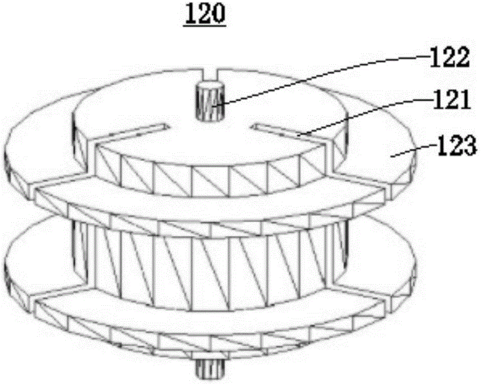
[0035] This embodiment provides a fluid power conversion device 100 . The fluid power conversion device 100 has an outer stator inner rotor structure. The fluid power conversion device 100 includes a stator 110 , a rotor 120 , a barrier plate 130 and a slider 140 . The stator 110 has a cylindrical shape. The rotor 120 is cylindrical.

[0036] The rotor 120 is rotatably provided inside the stator 110 . An annular cavity 150 is formed between the opposite side walls of the rotor 120 and the stator 110 . The cross-sectional shape of the annular cavity 150 is a regular annular shape. An inlet 111 and an outlet 112 are opened on the stator 110 . The blocking plate 130 is fixedly connected to the stator 110 and is slidably connected to the rotor 120 . The barrier plate 130 is located in the annular cavity 150 and between the inl...

no. 2 example

[0053] This embodiment provides a fluid power conversion device 100 , which differs from the fluid power conversion device in the first embodiment in that the fluid power conversion device 100 provided in this embodiment has an outer rotor inner stator structure.

[0054] Figure 5 For the schematic structural diagram of the fluid power conversion device provided in this embodiment, please refer to Figure 5 .

[0055] The stator 110 is cylindrical. An inlet 111 and an outlet 112 are opened on the stator 110 . The rotor 120 has a cylindrical shape. The rotor 120 is rotatably sleeved on the periphery of the stator 110 . An annular cavity 150 is formed between the rotor 120 and the stator 110 . Both the inlet 111 and the outlet 112 communicate the annular cavity 150 with the outside. The blocking plate 130 is fixedly connected to the stator 110 and is slidably connected to the rotor 120 . The barrier plate 130 is located in the annular cavity 150 and between the inlet 111...


PUM


Abstract

The invention relates to a hydrodynamic force conversion device and relates to the field of hydrodynamic force conversion. The hydrodynamic force conversion device comprises a stator, a rotor, a barrier plate and slide blocks. The rotor is rotatably connected to the stator, an annular cavity is formed between the relative side walls of the rotor and the stator, an inlet and an outlet are formed in the stator, the barrier plate is fixedly connected to the stator and is slidably connected to the rotor, and the barrier plate which is located in the annular cavity is arranged between the inlet and the outlet; chutes are formed on the surface, corresponding to the annular cavity, of the rotor; the slide block is arranged in each of the chutes; the slide blocks extend out from the chutes and divide the annular cavity together with the barrier plate into two sub-cavities which are different in pressure; and the slide block retracts back into the chutes so as to cross the barrier plate. The hydrodynamic force conversion device is simple in structure, and the mutual transformation efficiency of kinetic energy and mechanical energy of a fluid is high.

Description

technical field [0001] The invention relates to the field of fluid power conversion, in particular to a fluid power conversion device. Background technique [0002] The internal pressure chamber of the existing gas turbine or water turbine is not sealed, and a large amount of gas or liquid is lost from the gap in the pressure chamber, so that the gas turbine or water turbine cannot obtain continuous and stable torque, so that the existing gas turbine or water turbine The energy conversion efficiency of water turbine is low. Therefore, the existing gas turbine or water turbine not only has a complicated structure, but also has low energy conversion efficiency. Contents of the invention [0003] The object of the present invention is to provide a fluid power conversion device, which aims to solve the technical problems of the existing gas turbine or water turbine not only with complex structure, but also with low energy conversion efficiency. [0004] The present invention...

Claims


Application Information

Patent Timeline
Patent Type & Authority Applications(China)
IPC IPC(8): F01C1/344F03C2/30
CPCF01C1/344F03C2/30F03C2/304
Inventor 唐翊翃唐立唐静
Owner 唐翊翃
Why Eureka
Try Eureka