
a rotary compressor

A technology of rotating compressors and bodies, applied in the field of air-conditioning compressors, which can solve problems such as wear at the lower end of the eccentric part of the crankshaft, and achieve the effect of small space

Active Publication Date: 2020-06-16
GREE ELECTRIC APPLIANCES INC +1
View PDF7 Cites 0 Cited by
  • Summary
  • Abstract
  • Description
  • Claims
  • Application Information

AI Technical Summary

Problems solved by technology

[0005] Therefore, the technical problem to be solved by the present invention is to overcome the defect that the lower end of the crankshaft eccentric part in the prior art abuts against the second bearing, which causes the lower end of the crankshaft eccentric part to wear when the crankshaft rotates, thereby providing a method that can prevent the eccentricity of the crankshaft. Rotary compressors where the first and second bearings are worn

Method used


Image

  • a rotary compressor
  • a rotary compressor
  • a rotary compressor

Examples


Embodiment 1

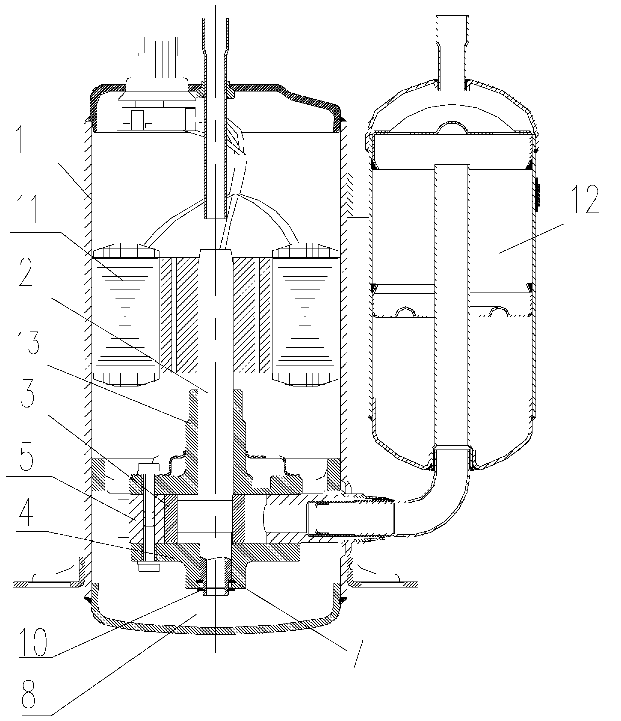
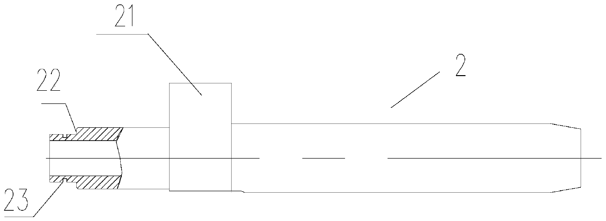
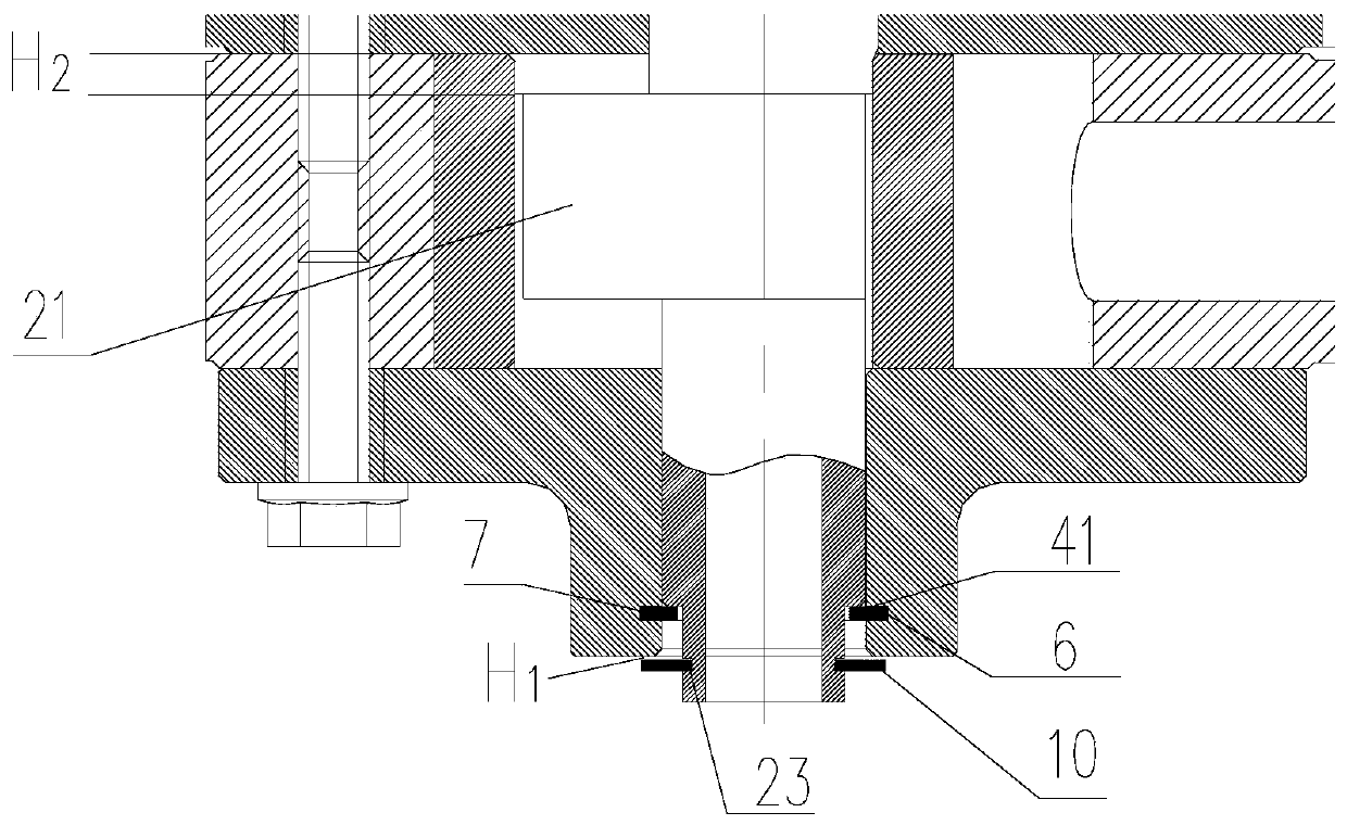
[0035] Such as figure 1 As shown, this embodiment provides a rotary compressor, including: a machine body 1; a crankshaft 2 with an eccentric portion 21, rotatably through the first bearing 3 and the second bearing 4 sleeved on both sides of the eccentric portion 21 Installed in the body 1; through the eccentric part 21, the cylinder 5 arranged in the body is driven to perform compressed gas work; between the second bearing 4 and the corresponding connection part of the crankshaft 2, an axial The limiting structure is used to maintain an axial gap between the eccentric portion 21 and the second bearing 4 .

[0036] That is, through the limiting structure, the crankshaft 2 can be lifted to a certain height, thereby preventing the contact between the eccentric portion 21 and the second bearing 4, thereby avoiding friction between the two to generate noise and cause compression Machine power consumption increases.

[0037] Such as figure 1 As shown, the rotary compressor in th...

Embodiment 2

[0052] In this embodiment, on the basis of the above-mentioned embodiment 1, the second bearing 4 is replaced by a radially narrowed part formed on the inner lower part, the transition surface of the radially reduced part is perpendicular to the rotation axis of the crankshaft 2, and the The transition surface of the radially narrowing portion forms said support surface 41 . The second bearing 4 shrinks radially inwardly to form a support surface 41, and the support surface 41 supports the bearing surface 22 of the crankshaft 2, so that the crankshaft 2 rotates vertically on the support surface 41, due to the contact between the two The area is small, so the friction generated is very small, which can effectively prevent the noise generated by friction.

[0053] As a transformable embodiment, in this embodiment, the rotary compressor described in the above-mentioned Embodiment 1 or Embodiment 2 is replaced by a horizontal position, and due to the axial limit structure, the ecc...


PUM


Abstract

Disclosed is a rotary compressor, comprising: a machine body (1); and a crankshaft (2) having an eccentric portion (21), wherein the crankshaft is rotatably mounted within the machine body (1) by means of a first bearing (13) and a second bearing (4) sleeved on two sides of the eccentric portion (21) and drives a cylinder (5) arranged inside the machine body by means of the eccentric portion (21) so as to work by compressing air. An axial limiting structure is provided between corresponding connecting portions of the second bearing (4) and the crankshaft (2) to maintain an axial gap between the eccentric portion (21) and the second bearing (4). The rotary compressor lifts the crankshaft to a certain level by means of the axial limiting structure to prevent the contact between the eccentric portion and the second bearing, so as to prevent noise produced due to friction between the two, causing an increase in power consumption of the compressor.

Description

technical field [0001] The invention relates to the technical field of air-conditioning compressors, in particular to a rotary compressor capable of preventing wear on the upper and lower surfaces of an eccentric part of a crankshaft. Background technique [0002] Rotary compressors are widely used in air-conditioning compressors and other fields to pressurize the condensing agent, and the condensing agent releases heat at the compressor. [0003] In the prior art, the compressor includes a body, the first bearing is installed inside the body, the second bearing is installed on one side of the first bearing, a cylinder is installed between the first bearing and the second bearing, and the crankshaft passes through the motor assembly and the second bearing in turn. A bearing is installed inside the cylinder, and one end of the crankshaft in the cylinder is formed with an eccentric part that deviates from the axis, and rollers are installed on the eccentric part. A high-press...

Claims


Application Information

Patent Timeline
Patent Type & Authority Patents(China)
IPC IPC(8): F04C29/00F04C29/02F04C29/06
CPCF04C29/00F04C29/02F04C29/06F04C2240/50F04C2240/80
Inventor 赵旭敏叶晓飞竺宁凯陈辉王伟
Owner GREE ELECTRIC APPLIANCES INC
Learn More