Testing apparatus for service life of load of valve execution mechanism and using method thereof

A valve execution, load life technology, applied in the testing of machine/structural components, measuring devices, testing of mechanical components, etc., can solve problems such as inability to provide constant load, easy deformation of disc springs, uncontrollable torque, etc. The load life test data is real, the torque adjustment is convenient, and the torque is stable.

Inactive Publication Date: 2017-02-01
TEFULONG SHANGHAI TECH CO LTD
View PDF7 Cites 8 Cited by
  • Summary
  • Abstract
  • Description
  • Claims
  • Application Information

AI Technical Summary

Problems solved by technology

[0006] First of all, since the friction force of the device is generated by the deformation of the disc spring, once the force applied to the disc spring is determined, the spring force generated by the disc spring is also determined, so the friction force or load and damping are also determined, that is It can only correspond to one kind of load during the test and cannot be changed during the test, so the versatility of the device is poor;
[0007] Secondly, this type of device generates a lot of heat during operation, and the change of temperature has a great influence on the elasticity of the disc spring. Therefore, the torque of this device is uncontrollable. During the test, it cannot provide a constant load as a test. standard;
[0008] In addition, this kind of device is easy to get stuck during use, and the disc spring is also easy to deform and fall out, resulting in loading failure.

Method used


Image

  • Testing apparatus for service life of load of valve execution mechanism and using method thereof

Examples


Embodiment

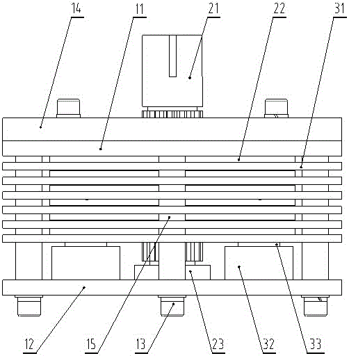
[0038] Such as figure 1 A structural schematic diagram of a valve actuator load life testing device provided by the present invention is as follows:

[0039] A valve actuator load life testing device, including a frame, a rotating mechanism and a loading mechanism;

[0040] The frame includes a top plate 11, a bottom plate 12 and more than three pillars 13; the pillars 13 are supported between the top plate 11 and the bottom plate 13 to form a machine cavity, and the top plate 11 is also covered with a test board 14 for placing the actuator;

[0041] The rotating mechanism includes a rotating shaft 21, a rotating disk 22 and a bearing 23; bearings 23 are respectively installed in the center of the top plate 11 and the bottom plate 12, the rotating shaft 21 is installed in the two bearings 23 and the upper end passes through the top plate 11 and the mounting plate 14, more than one The rotating disc 22 is installed horizontally on the rotating shaft 21 in the machine cavity an...


PUM


Abstract

The invention provides a testing apparatus for a service life of a load of a valve execution mechanism and a using method thereof. The testing apparatus comprises a rack, a rotating mechanism and a loading mechanism. The rack is supported between a top plate and a bottom plate by support posts. A testing plate covers the top plate. Rotating shafts are installed in bearings between the top plate and the bottom plate and the upper ends of the rotating shafts pass out of the top plate and a mounting plate. More than one rotating plate is installed on the rotating shafts horizontally and rotates with the rotating shafts. The loading mechanism includes friction plates and hydraulic systems; through holes are formed in the friction plates and the friction plates sleeve the support posts through the through holes. One friction plate is arranged below each rotating plate; and the friction plates are separated by sleeving rings arranged on the support posts. The hydraulic systems are installed on the bottom plate and mandrils of the hydraulic systems support the bottom friction plates; under pushing of the mandrils, upward contact with the rotating plates is realized and the last friction plate is pushed upwardly by the sleeving ring and is in contact with the rotating plate arranged on the friction plate; and the rotating plates and the friction plates in close contact with the rotating plates respectively generate friction and the friction forces are transformed into torques by the rotating shafts, thereby realizing testing of the service life of the load of the valve execution mechanism.

Description

technical field [0001] The invention relates to a device for testing the load life of a valve actuator and a method for using the same, belonging to the technical field of valve actuator quality detection. Background technique [0002] Valve actuators usually work under load. Therefore, the service life of valve actuators under load is an important quality and technical index of valve actuators. The most objective and fair way to investigate this technical index is of course the actual inspection during actual production and application. However, such actual inspection cannot be carried out on every valve actuator. Therefore, samples are taken according to certain rules. , and testing through laboratory loading tests has become an important method to investigate the service life of valve actuators under load conditions. [0003] When testing the load life of valve actuators in the laboratory, a load must first be added to the valve actuators, and then the test measurement i...

Claims


Application Information

Patent Timeline
Patent Type & Authority Applications(China)
IPC IPC(8): G01M13/00
CPCG01M13/00
Inventor 朱营博苗义修红学
Owner TEFULONG SHANGHAI TECH CO LTD
Why Eureka
Try Eureka