Traveling wave ultrasonic motor containing flexible shaft

An ultrasonic motor, flexible shaft technology, applied in the direction of generator/motor, piezoelectric effect/electrostrictive or magnetostrictive motor, electrical components, etc., can solve the problems of poor motor running stability and poor uniformity, and achieve enhanced The effect of load capacity, elimination of clearance, and improvement of operating stability

Active Publication Date: 2017-02-01
NINGBO UNIV
View PDF8 Cites 4 Cited by
  • Summary
  • Abstract
  • Description
  • Claims
  • Application Information

AI Technical Summary

Problems solved by technology

[0004] The present invention aims to solve the problems of poor contact uniformity of the stator and rotor of the existing traveling wav

Method used


Image

  • Traveling wave ultrasonic motor containing flexible shaft
  • Traveling wave ultrasonic motor containing flexible shaft
  • Traveling wave ultrasonic motor containing flexible shaft

Examples


specific Embodiment approach 1

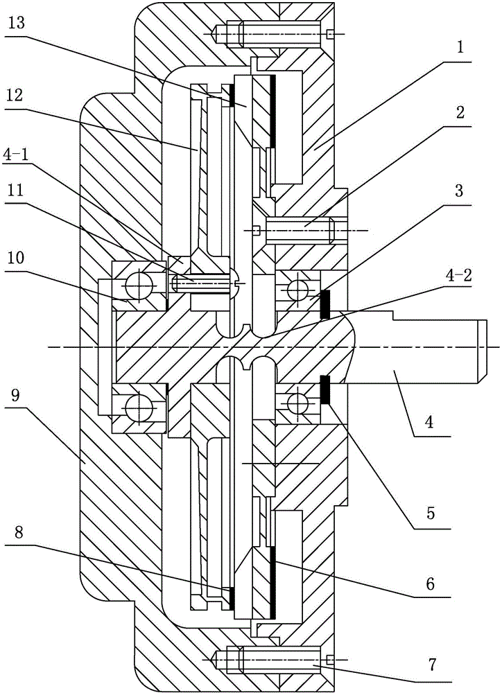
[0018] Specific implementation mode one: combine Figure 1-Figure 3 Explain that a traveling wave ultrasonic motor with a flexible shaft in this embodiment includes a base 1, a front angular contact ball bearing 3, a flexible shaft 4, a housing 9, a rear angular contact ball bearing 10, a rotor 12 and a stator 13;

[0019] The housing 9 and the base 1 are detachably connected, the base 1 is equipped with a front angular contact ball bearing 3, the housing 9 is equipped with a rear angular contact ball bearing 10, and the flexible shaft 4 is installed on the front angular contact ball bearing 3 and the rear angular contact ball bearing 10; the rotor 12 and the stator 13 are arranged between the front angular contact ball bearing 3 and the rear angular contact ball bearing 10, the rotor 12 is arranged adjacent to the housing 9 and installed on the annular rib 4-1 of the flexible shaft 4, The stator 13 is installed on the base 1, a layer of annular friction material 8 in contact ...

specific Embodiment approach 2

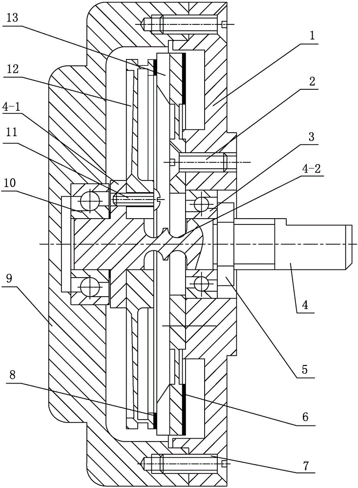
[0025] Specific implementation mode two: combination figure 1 with figure 2 Note that a traveling wave ultrasonic motor with a flexible shaft in this embodiment further includes a circlip 5 , and the front angular contact ball bearing 3 preloads the inner ring of the stator 13 through the circlip 5 . With such setting, the preload is convenient, reliable and easy to use. Others are the same as in the first embodiment.

specific Embodiment approach 3

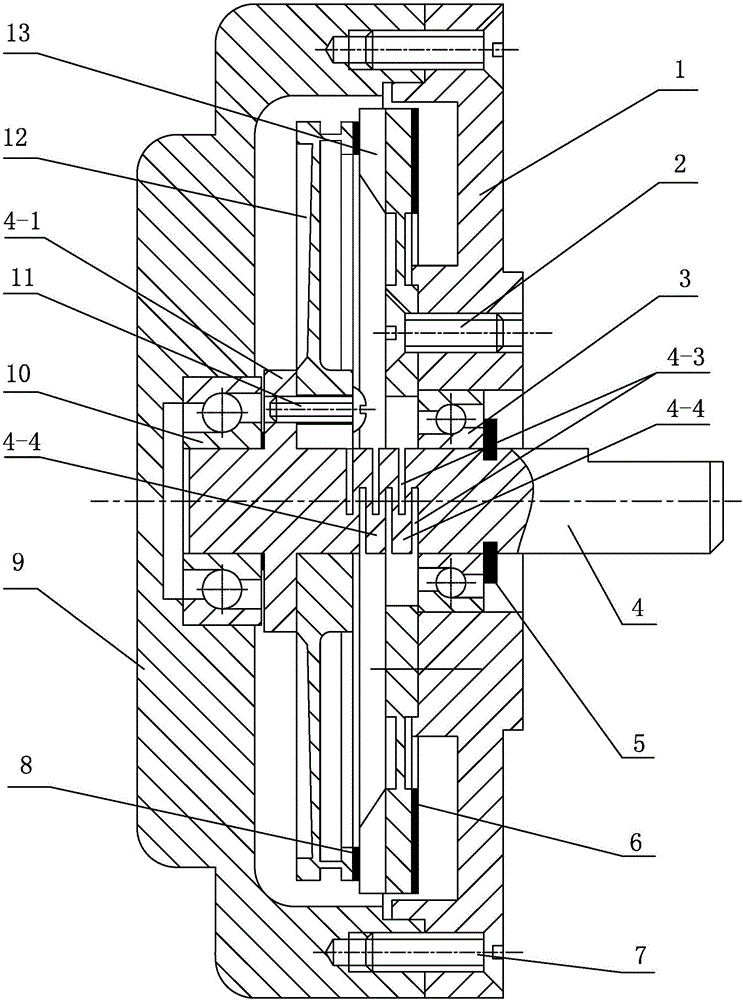
[0026] Specific implementation mode three: combination figure 1 with figure 2 Note that a traveling wave ultrasonic motor with a flexible shaft in this embodiment also includes a pre-tightening nut 15, the shaft section of the flexible shaft 4 close to the front angular contact ball bearing 3 is a threaded shaft section, and the pre-tightening nut 15 is screwed on the threaded shaft. On the shaft section, the front angular contact ball bearing 3 preloads the inner ring of the stator 12 through the preload nut 15 . In such a setting, the pre-tightening nut exerts a pre-tightening force, which improves the uniformity of the pre-pressure loading. When used with a flexible shaft, the motor's running stability and load capacity can be further improved. Others are the same as in the first embodiment.


PUM

PropertyMeasurementUnit
Wear rateaaaaaaaaaa
Wear rateaaaaaaaaaa

Abstract

The invention discloses a traveling wave ultrasonic motor containing a flexible shaft, relates to the traveling wave ultrasonic motor, and aims to solve the problems of poor uniformity of contact between a stator and a rotor and low operational stability of the motor of the existing traveling wave ultrasonic motor. The traveling wave ultrasonic motor comprises a base, a front angular contact ball bearing, a shell, the flexible shaft, a back angular contact ball bearing, a stator and a rotor, wherein the shell and the base are detachably connected; the flexible shaft is mounted on the front angular contact ball bearing and the back angular contact ball bearing; the rotor and the stator are arranged between the front angular contact ball bearing and the back angular contact ball bearing; the rotor and the shell are arranged adjacently, and are mounted on an annular convex prism of the flexible shaft; the stator is mounted on the base; a layer of annular friction material which is in contact with the stator is paved on the end plane of the rim of the rotor; an annular piezoelectric ceramic layer is paved on the end plane, close to the base, of the stator; and a flexible hinge structure or a flexible foldable beam structure is machined on the shaft section of the flexible shaft positioned between the rotor and the stator. The traveling wave ultrasonic motor is used for accurate driving.

Description

technical field [0001] The invention relates to a traveling wave ultrasonic motor, in particular to a traveling wave ultrasonic motor with a flexible shaft. The utility model belongs to the field of piezoelectric drive technology. Background technique [0002] Ultrasonic motor is a new type of micro motor that converts electrical energy into mechanical energy by using the inverse piezoelectric effect of piezoelectric materials. The stator of an ultrasonic motor is usually a composite elastic body of a specific shape composed of piezoelectric ceramics and metal elastomers. By applying an AC voltage of ultrasonic frequency to the piezoelectric ceramics, the mechanical vibration of the same frequency in the stator elastic body is excited, and then on the surface of the stator Form a motion trajectory with a driving effect. Generally, the trajectory of the particle is an ellipse. Through the frictional coupling between the stator and the rotor, the output of the macroscopic mot...

Claims


Application Information

Patent Timeline
IPC IPC(8): H02N2/16
CPCH02N2/16
Inventor 李锦棒崔玉国于爱兵刘洋
Owner NINGBO UNIV
Why Eureka
Try Eureka