
Transmitting circuit topology of electromagnetic prospecting transmitter and control method thereof

A technology of transmitting circuits and transmitters, applied in the field of electronics, can solve the problems of large voltage stress of devices, large electromagnetic interference, and low utilization rate of transmitted waveform energy, achieve good stability, and reduce the effects of insulation shock and electromagnetic interference.

Inactive Publication Date: 2017-02-01
INST OF GEOLOGY & GEOPHYSICS CHINESE ACAD OF SCI
View PDF5 Cites 0 Cited by
  • Summary
  • Abstract
  • Description
  • Claims
  • Application Information

AI Technical Summary

Problems solved by technology

[0002] The transmission topology of the electromagnetic survey transmitter usually adopts an H-bridge topology to transmit square wave signals of different frequencies. The traditional transmission topology and transmission waveforms use the H-bridge topology to transmit square waves of different frequencies, which has a simple structure. , easy to drive and other advantages, but there are also some shortcomings. Solving these shortcomings is a problem that must be faced to achieve special construction requirements such as high-power transmission and high-voltage transmission.
[0003] 1. Since the transmission is a square wave, the transmitted signal has more harmonic components, and the energy wasted by the harmonics is very objective. For example, the corresponding 5th harmonic is 1 / 5 of the fundamental wave, and the 7th harmonic It is 1 / 7 of the fundamental wave, so the energy utilization rate of this transmitted waveform is very low
[0004] 2. Since the output waveform has only two levels that alternate repeatedly, the voltage change rate is relatively high during the two-level alternation process, that is, there is a large du / dt, which makes the electromagnetic interference (EMI) of the system The problem is relatively large, the operating environment of the system is not good, the voltage stress of the device is relatively large, and the requirements for the withstand voltage of the device are relatively high
[0005] 3. Since the same bridge arm must avoid two switch tubes being turned on at the same time and cause a short-circuit fault in the power supply, the selection of the dead zone is very important, and the turn-on time and turn-off time of the device are not a fixed parameter, it varies with the temperature There is a large floating range, so there is also a problem in the selection of the dead zone
[0006] 4. Due to the high requirements for devices, H-bridges are simply used to achieve high voltage. There are difficulties in device selection for high-current transmission, and high-power transmission has high requirements for devices.

Method used


Image

  • Transmitting circuit topology of electromagnetic prospecting transmitter and control method thereof
  • Transmitting circuit topology of electromagnetic prospecting transmitter and control method thereof
  • Transmitting circuit topology of electromagnetic prospecting transmitter and control method thereof

Examples


Embodiment Construction

[0028] In order to enable those skilled in the art to better understand the solutions of the present invention, the following will clearly and completely describe the technical solutions in the embodiments of the present invention in conjunction with the drawings in the embodiments of the present invention. Obviously, the described embodiments are only It is an embodiment of a part of the present invention, but not all embodiments. Based on the embodiments of the present invention, all other embodiments obtained by persons of ordinary skill in the art without making creative efforts shall fall within the protection scope of the present invention.

[0029] The terms "first", "second", "third", "fourth", etc. (if any) in the description and claims of the present invention and the above drawings are used to distinguish similar objects and not necessarily Describe a specific order or sequence. It is to be understood that the terms so used are interchangeable under appropriate cir...


PUM


Abstract

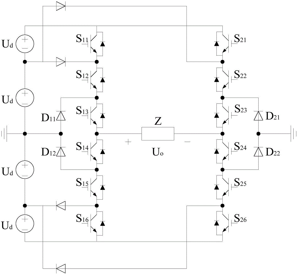
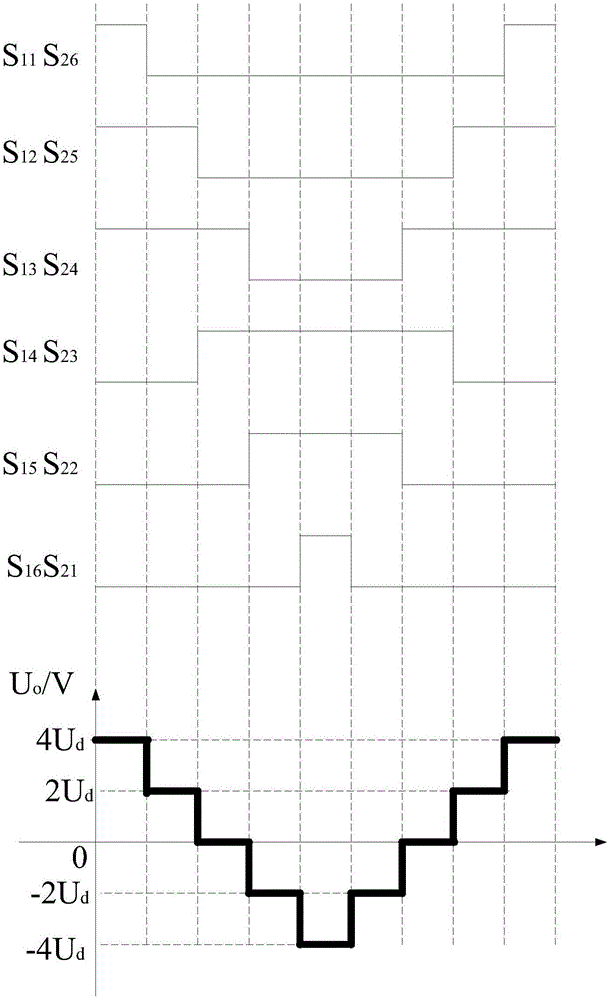
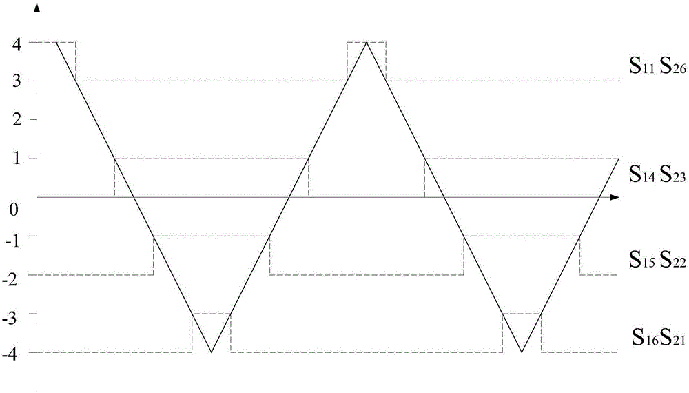
The embodiment of the invention discloses a transmitting circuit topology of an electromagnetic prospecting transmitter and a control method thereof. The transmitting circuit topology comprises a multi-level transmitting bridge circuit; and the multi-level transmitting bridge circuit comprises eight IGBT tubes, namely S11, S12, S13, S14, S15, S16, S21, S22, S23, S24, S25 and S26, and four clamping diodes, namely D11, D12, D21 and D22. The improved multi-level topology in a circuit clamps voltages of the clamping diodes within single levels, so the good stability is guaranteed; compared with an existing device, with relatively small dv / dt and di / dt, the transmitting circuit topology has reduced insulation impact and electromagnetic interference.

Description

technical field [0001] The invention relates to the field of electronics, in particular to a transmitting circuit topology of an electromagnetic survey transmitter and a control method thereof. Background technique [0002] The transmission topology of the electromagnetic survey transmitter usually adopts an H-bridge topology to transmit square wave signals of different frequencies. The traditional transmission topology and transmission waveforms use the H-bridge topology to transmit square waves of different frequencies, which has a simple structure. , easy to drive and other advantages, but there are also some shortcomings. Solving these shortcomings is a problem that must be faced to achieve special construction requirements such as high-power transmission and high-voltage transmission. [0003] 1. Since the transmission is a square wave, the transmitted signal has more harmonic components, and the energy wasted by the harmonics is very objective. For example, the corresp...

Claims


Application Information

Patent Timeline
IPC IPC(8): H03K3/021H03K3/013
CPCH03K3/013H03K3/021
Inventor 真齐辉底青云
Owner INST OF GEOLOGY & GEOPHYSICS CHINESE ACAD OF SCI
Learn More