

Wall plastering device and work method of same
A one-of-a-kind technology, applied in the field of plastering device and plastering device for painting building walls, can solve the problem of low precision, and achieve the effect of improving adjustment efficiency and flatness.
- Summary
- Abstract
- Description
- Claims
- Application Information
AI Technical Summary
Problems solved by technology
Method used
Image

Examples
Embodiment 1
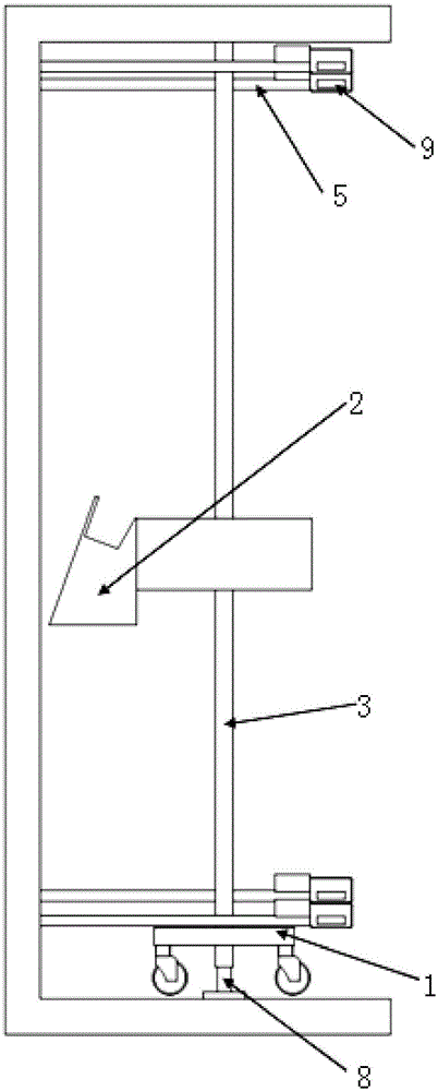
[0037] Example 1 as Figure 1-Figure 2As shown, the wall wiping device of the present embodiment comprises a base frame 1, a wall wiping machine head 2, two telescopic upright rails 3 connected and fixed on the base frame 1, a hydraulic cylinder 8 device as a lifting device, two The upright track 3 is a rectangular cylinder, and the wall plastering machine head 2 is installed on the side of the two upright tracks 3 close to the wall 6 to be constructed, and the two vertical upright tracks 3 maintain a fixed position on the wall 6 to be constructed. spacing, the upper and lower ends of each upright track 3 are also provided with an electric push rod device 5 for adjusting the distance between the upright track 3 and the wall surface 6 to be constructed, and the electric push rod device 5 is fixedly connected with the upright track 3 through the housing. And the screw mandrel of electric push rod device 5 is vertically arranged with upright rail 3, and the housing of electric pu...
Embodiment 2
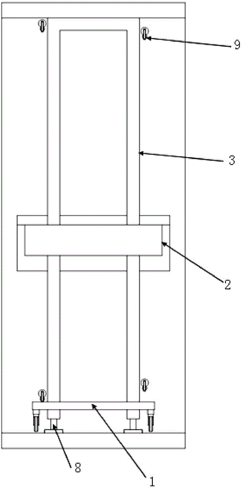
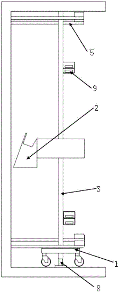
[0042] Such as figure 2 As shown, the difference between this embodiment and Embodiment 1 is that a receiving controller 9 is also provided on the same side at the upper and lower ends of each upright rail 3, and the receiving positions of each receiving controller 9 are in the same plane when working. . The electric push rod device 5 is no longer provided, and the upright track 3 is manually adjusted to be close to or away from the wall surface 6 to be constructed during use. This embodiment also includes an auxiliary laser generating device, using the auxiliary laser generating device to simulate a virtual wall parallel to the wall surface 6 to be constructed, and this virtual wall surface is the surface reached after the wall surface 6 to be constructed has completed the plastering operation. , can effectively ensure that the plastered wall covers any point on the wall to be constructed. The specific work steps include: according to the thickness of the plastering requir...
PUM
 Abstract
Description
Claims
Application Information