
F-type loading improvement floor broadband omnidirectional circular polarization printing antenna

A printed antenna and circular polarization technology, which is applied in the field of broadband omnidirectional circularly polarized printed antennas, can solve the problems of narrow impedance bandwidth and axial ratio bandwidth, and achieve the effects of easy integration, easy conformality, and low profile

Active Publication Date: 2017-02-08
HARBIN INST OF TECH
View PDF4 Cites 3 Cited by
  • Summary
  • Abstract
  • Description
  • Claims
  • Application Information

AI Technical Summary

Problems solved by technology

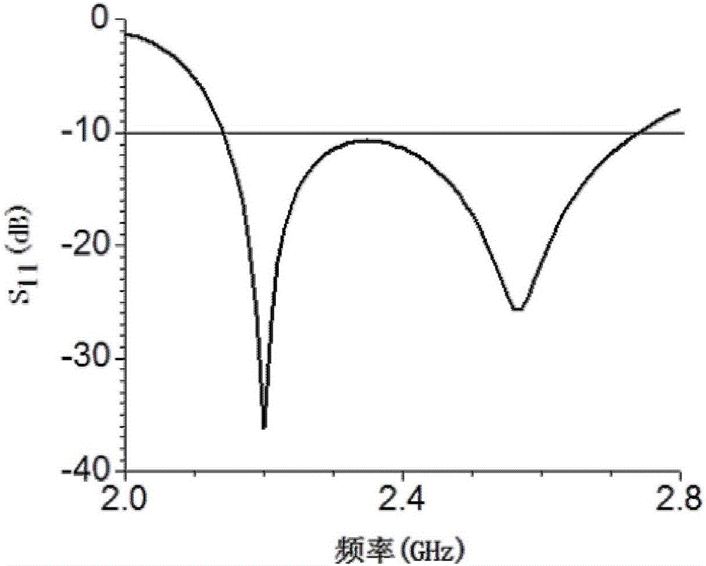
[0003] The purpose of the present invention is to solve the problem that the impedance bandwidth and the axial ratio bandwidth of the existing broadband omnidirectional circularly polarized printed antenna are too narrow, and to provide a broadband omnidirectional circularly polarized printed antenna with F-type loading and improved floor

Method used


Image

  • F-type loading improvement floor broadband omnidirectional circular polarization printing antenna
  • F-type loading improvement floor broadband omnidirectional circular polarization printing antenna
  • F-type loading improvement floor broadband omnidirectional circular polarization printing antenna

Examples


specific Embodiment approach 1

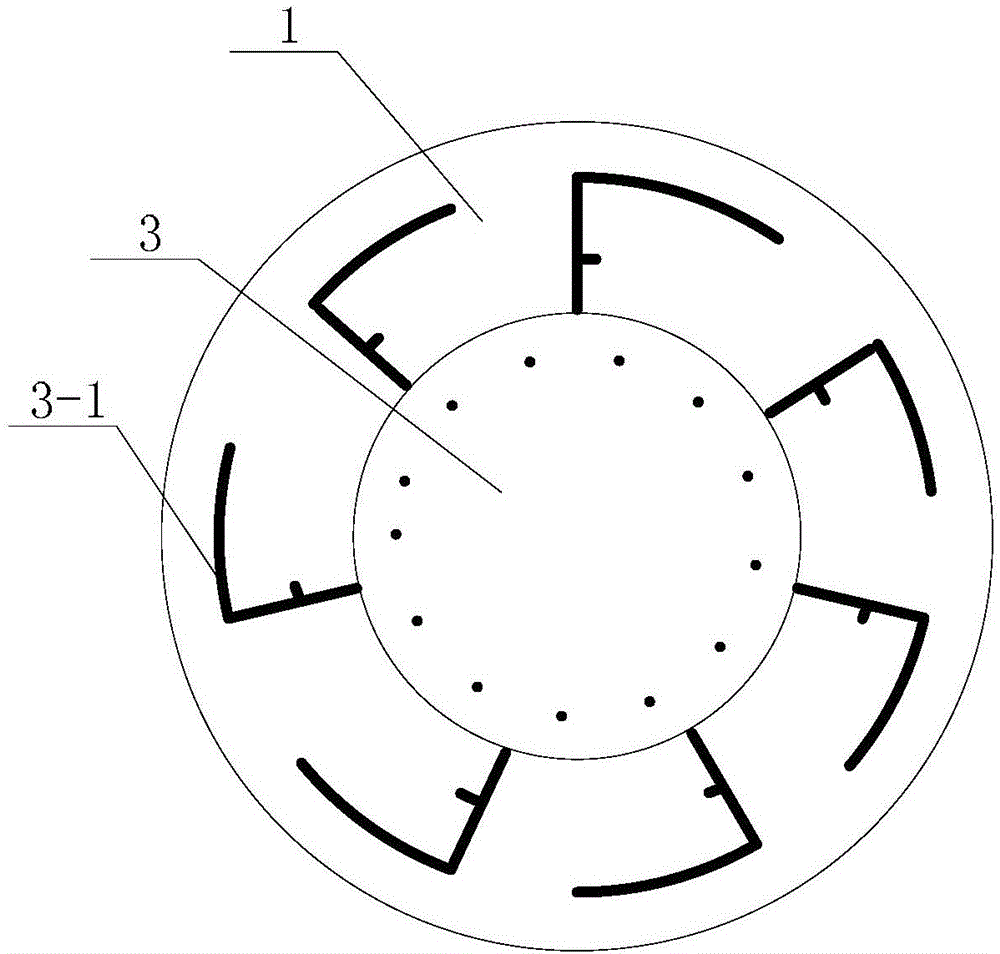
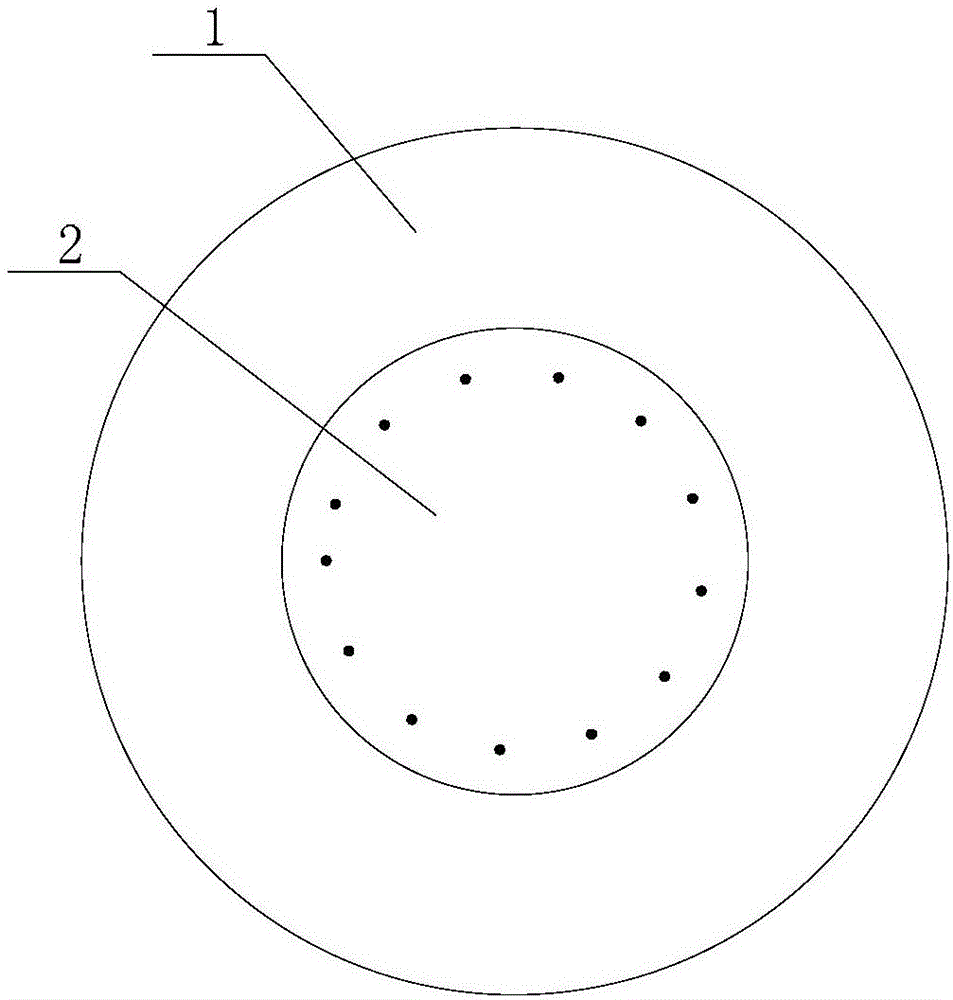
[0028] Specific implementation mode one: the following combination Figure 1 to Figure 5 Describe this embodiment, the F-type broadband omnidirectional circularly polarized printed antenna loaded with improved floor in this embodiment, it includes a dielectric substrate 1, it also includes an upper radiation patch 2 and a lower floor 3,

[0029] Both the dielectric substrate 1 and the upper radiation patch 2 are circular; the lower floor 3 is a circular metal floor with F-shaped branches 3-1 on the outer circumference;

[0030] The upper radiation patch 2 is printed on the upper surface of the dielectric substrate 1, and the lower floor 3 is printed on the lower surface of the dielectric substrate 1. The centers of the dielectric substrate 1, the upper radiation patch 2 and the lower floor 3 are coaxial, and coaxial Probe feed;

[0031] The corresponding positions of the dielectric substrate 1, the upper radiation patch 2 and the lower floor 3 are uniformly distributed with a...


PUM


Abstract

The present invention provides an F-type loading improvement floor broadband omnidirectional circular polarization printing antenna, belonging to the broadband omnidirectional circular polarization printing antenna field. The objective of the invention is to solve the problem that the current broadband omnidirectional circular polarization printing antenna has too narrow impedance bandwidth and axial ratio bandwidth. The dielectric substrate and an upper layer radiation paster are in circle shape; a lower layer floor is a circle metal floor having an external circumference with an F-type branch; the upper layer radiation paster is printed on the upper surface of the dielectric substrate, the lower layer floor is printed at the lower surface of the dielectric substrate, the circle centers of the dielectric substrate, the upper layer radiation paster and the lower layer floor are coaxial, and the coaxial probe feed is performed; the corresponding boreholes of the dielectric substrate, the upper layer radiation paster and the lower layer floor are connected through metal through holes; the external circumference of the lower layer floor uniformly distributes 5-10 F-type branches. The present invention provides a broadband omnidirectional circular polarization printing antenna.

Description

technical field [0001] The invention relates to a broadband omnidirectional circularly polarized printed antenna, in particular to a wideband omnidirectional circularly polarized printed antenna with an F-type loading improved floor. Background technique [0002] Omnidirectional antennas can provide larger signal coverage than traditional directional antennas, and it can maintain real-time communication between vehicle-mounted equipment or mobile terminals and targets at different azimuths around them; circularly polarized antennas can effectively suppress multipath fading and polarization loss. The loss caused by matching can ensure the stability of signal transmission; printed antennas have very broad application prospects due to their advantages such as low profile, easy conformality, easy integration, and low cost. The broadband omnidirectional circularly polarized printed antenna combines the excellent antenna characteristics of low profile, broadband, omnidirectionalit...

Claims


Application Information

Patent Timeline
Patent Type & Authority Applications(China)
IPC IPC(8): H01Q1/36H01Q1/38H01Q1/50
CPCH01Q1/36H01Q1/38H01Q1/50
Inventor 张赫谷海川宗华
Owner HARBIN INST OF TECH
Learn More