Eureka AIR delivers breakthrough ideas for toughest innovation challenges, trusted by R&D personnel around the world.

Milling device of perfect binding machine for tabletop

A glue binding machine and milling technology, which is applied in the field of milling devices, can solve problems affecting the normal use of books, paper scraps cannot be cleaned in time, and affect the quality of glue coating, etc., and achieve the goals of improving binding quality, timely paper scraps, and convenient operation Effect

Active Publication Date: 2017-02-15
HUZHOU JIANING PRINTING
View PDF6 Cites 4 Cited by
  • Summary
  • Abstract
  • Description
  • Claims
  • Application Information

AI Technical Summary

Problems solved by technology

When the milling cutter is milling the spine, the milling height needs to be manually adjusted, which will cause errors, affect the milling precision, and then reduce the quality of the binding; at the same time, because a large number of small waste paper scraps, some flying waste paper scraps will affect the operating environment, and the waste paper scraps attached to the spine will make the glue not easy to stick to the spine when gluing, affecting the quality of glue coating; moreover, the existing clips The clamping mechanism is far away from the milling cutter, resulting in insufficient clamping force at the spine of the book, making it easy for the milling cutter to damage the paper during milling, affecting the normal use of the book
Therefore, the existing technology has problems such as low milling precision, inconvenient operation, unable to clean up paper scraps in time, affecting the working environment, low binding quality, and easily damaged paper.

Method used


Image

  • Milling device of perfect binding machine for tabletop
  • Milling device of perfect binding machine for tabletop

Examples


Embodiment Construction

[0013] The present invention will be further described below in conjunction with the accompanying drawings and examples, but not as a basis for limiting the present invention.

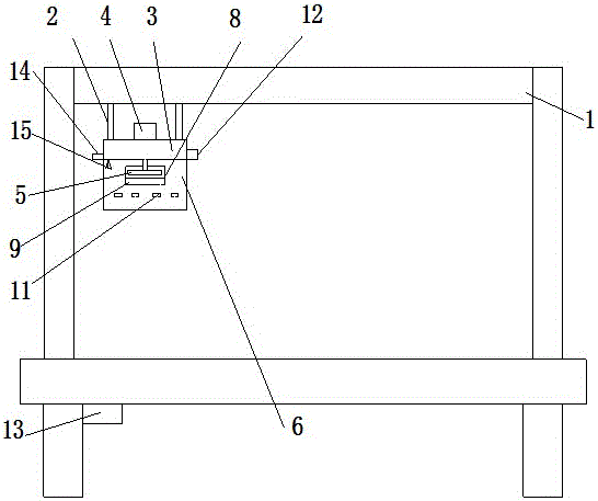
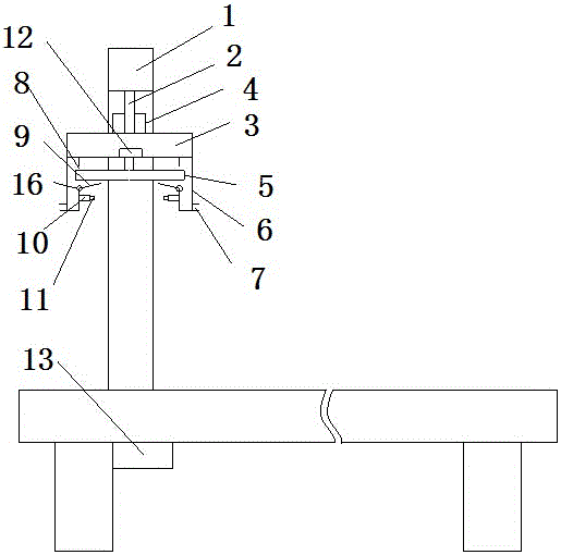
[0014] Example. The milling and grinding device of the desktop glue binding machine is composed of figure 1 and figure 2 As shown, it includes a hydraulic rod 2 fixed on the slide rail 1 of the adhesive binding machine. The end of the hydraulic rod 2 is provided with a fixed plate 3, and a motor 4 is provided above the fixed plate 3. The motor 4 is connected to a milling cutter 5, and the milling cutter 5 is located at The bottom of the fixed plate 3; the two sides below the fixed plate 3 are provided with a dust suction shell 6, the bottom of the outer side of the dust suction shell 6 is provided with a dust suction pipe 7, and the inside of the dust suction shell 6 is provided with the position of the milling cutter 5 Corresponding to the dust suction opening 8, the lower end of the dust suction o...


PUM


Abstract

The invention discloses a milling device of a perfect binding machine for a tabletop, comprising a hydraulic rod (2); the end of the hydraulic rod (2) is provided with a fixed plate (3), and a motor (4) is arranged above the fixed plate (3) and is connected with a milling cutter (5); a dust suction shell (6) is arranged below the fixed plate (3), the bottom of the dust suction shell (6) is provided with a dust suction pipeline (7), a dust suction opening (8) is formed in the inner side of the dust suction shell (6), and the lower end of the dust suction opening (8) is provided with a baffle (9); the inner side of the dust suction shell (6) is provided with a pressing wheel (11); and one end of the fixed plate (3) is provided with an infrared sensor (12) connected with a controller (13), and the controller is connected with the hydraulic rod and a sliding rail (1). The milling device is relatively high in milling precision, convenient to operate and capable of clearing paper scraps in time, reducing influences to the environment, improving the binding quality and reducing the damage rate of paper sheets.

Description

technical field [0001] The invention relates to a milling device, in particular to a milling device for a desktop glue binding machine. Background technique [0002] The emergence of desktop binding machines enables users to easily produce exquisite contracts, meeting manuals, briefings, operating instructions, tenders, insurance policies and personalized notebooks in the unit. It has the advantages of less electricity, fast binding, high thickness limit of glue binding, and simple operation, replacing the traditional plastic clamping strips. When the desktop binding machine is in production, the paper to be bound is put into the clamp first, then the spine of the book is polished with a milling cutter, and then the spine is glued, and finally the spine is fixed and cooled to complete. When the milling cutter is milling the spine, the milling height needs to be manually adjusted, which will cause errors, affect the milling precision, and then reduce the quality of the bindi...

Claims


Application Information

Patent Timeline
Patent Type & Authority Applications(China)
IPC IPC(8): B23C3/00B23Q3/06B23Q11/00
CPCB23C3/00B23C2226/54B23Q3/062B23Q11/0046
Inventor 虞建强虞东杰
Owner HUZHOU JIANING PRINTING
Why Eureka
Eureka Blog
Learn More