

Semiautomatic stripping device for discharging die
A stripping device and semi-automatic technology, applied in metal processing and other directions, can solve problems such as cracking, product deformation, and inability to ensure uniform force on the positioning needle, and achieve the effect of improving processing efficiency and improving pass rate.
Inactive Publication Date: 2017-02-15
江苏弘信华印电路科技有限公司
View PDF6 Cites 0 Cited by
- Summary
- Abstract
- Description
- Claims
- Application Information
AI Technical Summary
Problems solved by technology
[0002] The current blanking mold is to put the product on the positioning pin and punch it. After the punching is completed, the product is pulled out from the positioning pin by hand. When we pull the product by hand, we cannot guarantee that the positioning pin will come out when the product is pulled out. Uniform force, which is easy to cause product deformation, cracking and other phenomena
Method used
View moreImage
Smart ImageViewing Examples

Examples
Embodiment Construction
[0014] In order to make the technical solution of the present invention clearer, the present invention will be further described below in conjunction with the accompanying drawings. Any solution obtained by equivalent replacement and conventional reasoning of the technical features of the technical solution of the present invention falls within the protection scope of the present invention.
Login to View More PUM
 Abstract
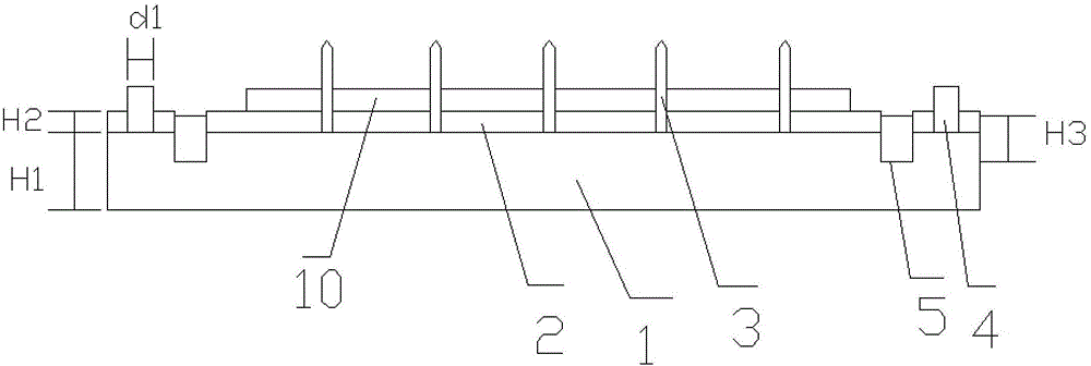
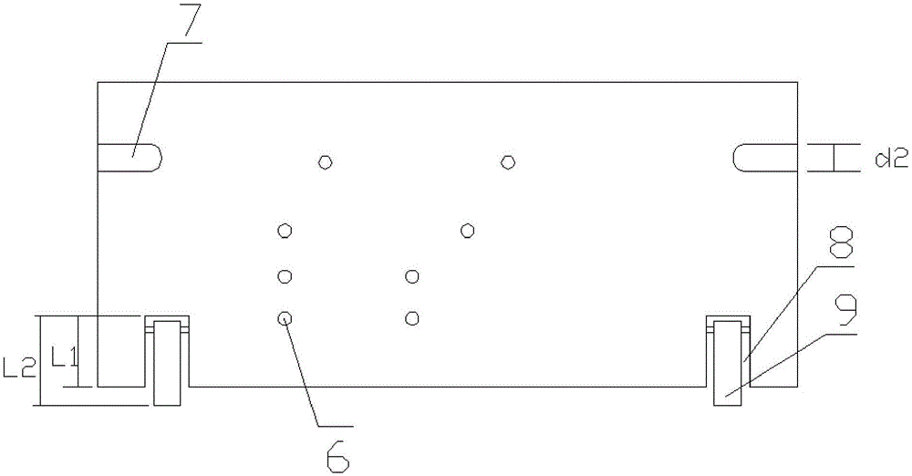
The invention relates to a semiautomatic stripping device for a discharging die. The semiautomatic stripping device comprises a bottom plate and a stripping plate. Multiple positioning needles and two positioning pins are arranged on the bottom plate. The positioning pins are fixed to the two sides of the bottom plate. The positioning needles are arranged between the two positioning pins. The bottom plate is provided with two first stripping handle fixing grooves. The stripping plate is provided with multiple positioning needle through holes and two positioning pin through holes. The stripping plate is provided with two second stripping handle fixing channels which correspond to the first stripping handle fixing grooves. A stripping handle is rotationally fixed in each second stripping handle fixing channel through a rotating shaft. The stripping plate is arranged above the bottom plate so that the positioning needles can penetrate the positioning needle through holes and the positioning pins can penetrate the positioning pin through holes, stripping handles are placed in the first stripping handle fixing grooves, the phenomena of hole deformation and base plate deformation and tearing caused by manually dragging the discharging die are avoided, the qualification rate of products is increased, and the machining efficiency is improved.
Description
technical field [0001] The invention relates to a stripping device, in particular to a semi-automatic stripping device for a blanking mold. Background technique [0002] The current blanking mold is to put the product on the positioning pin and punch it. After the punching is completed, the product is pulled out from the positioning pin by hand. When we pull the product by hand, we cannot guarantee that the positioning pin will come out when the product is pulled out. Uniform force, which is easy to cause product deformation, cracking and other phenomena. Contents of the invention [0003] Aiming at the above problems, the present invention proposes a semi-automatic stripping device for the blanking mold, which solves the phenomenon of hole deformation, substrate deformation, and tearing caused by manually pulling the blanking mold, improves the pass rate of the product, and improves the processing efficiency . [0004] The specific technical scheme is as follows: [00...
Claims
Login to View More Application Information
Patent Timeline
 Patent Type & Authority Applications(China)
IPC IPC(8): B26F1/38B26F1/44B26D7/01B26D7/00
CPCB26F1/38B26D7/00B26D7/01B26F1/44B26F2210/08
Inventor 任大兴
Owner 江苏弘信华印电路科技有限公司