
cutter wheel

A cutting wheel and cutting edge technology, applied in manufacturing tools, other manufacturing equipment/tools, metal processing, etc., can solve problems such as the inability to precisely machine the size of the cutting edge and the inability to maintain the rotating surface horizontally.

Active Publication Date: 2021-08-24
MITSUBOSHI DIAMOND IND CO LTD
View PDF11 Cites 0 Cited by
  • Summary
  • Abstract
  • Description
  • Claims
  • Application Information

AI Technical Summary

Problems solved by technology

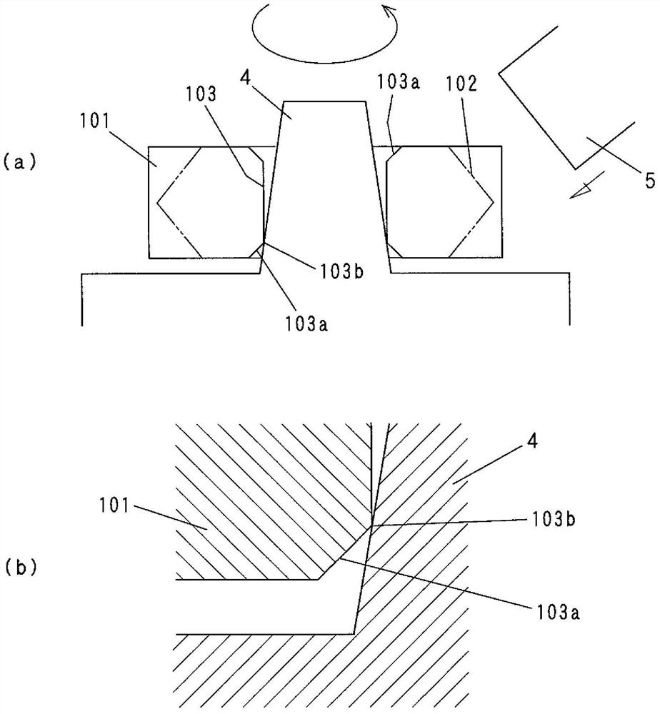
In addition, small irregularities may be caused on the surface of the tapered shaft 4 due to the hard and sharp corners 103b.
Since the disk-shaped main body 101 is supported by the tapered shaft 4 at the corner 103b, when such a flaw occurs, its posture is slightly inclined, and the rotation plane cannot be maintained horizontally.
Therefore, rotation vibration occurs and the blade size cannot be precisely machined

Method used


Image

  • cutter wheel
  • cutter wheel
  • cutter wheel

Examples


Embodiment Construction

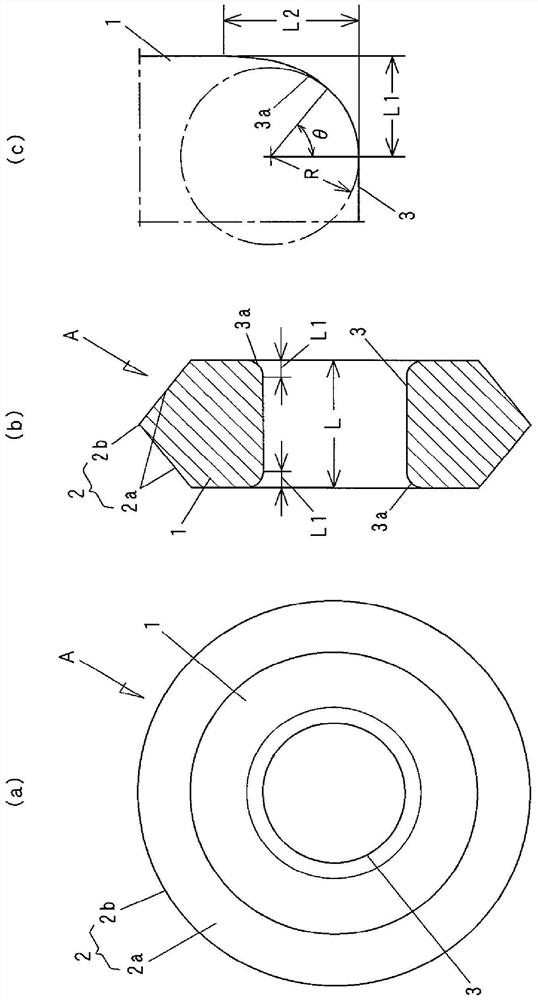
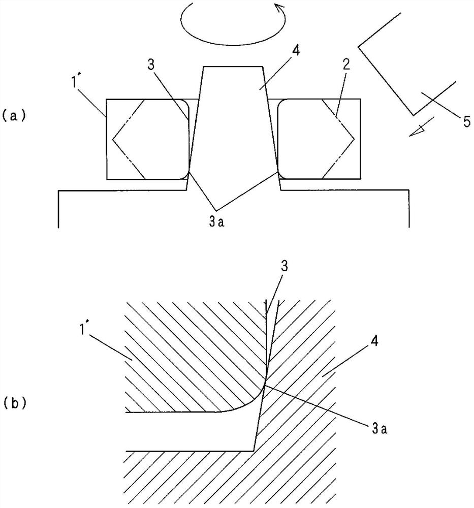
[0024] Below, based on figure 1 , figure 2 The cutter wheel of the present invention will be described in detail.

[0025] figure 1 It is a figure showing the cutter wheel A of the present invention, figure 1 (a) is the front view, figure 1 (b) is a side sectional view, figure 1 (c) is an enlarged view of the arc surface 3a portion of the bearing hole 3 . This cutter wheel A is made only of single crystal diamond, and a blade portion 2 is provided on the outer peripheral surface of a disk-shaped main body 1 having a bearing hole 3 penetrating the center. The blade portion 2 is composed of left and right slopes 2a, 2a and a ridge line 2b formed at the intersection of these slopes 2a, 2a. In this embodiment, the cutter wheel A is formed to have a diameter of 2 mm and a thickness of 650 μm.

[0026] The bearing hole 3 of the disc-shaped main body 1 is formed by a through hole with a constant inner diameter, and the opening edges at both ends thereof are formed by arc...


PUM

PropertyMeasurementUnit
diameteraaaaaaaaaa
diameteraaaaaaaaaa
diameteraaaaaaaaaa

Abstract

The present invention provides a cutter wheel made of single crystal diamond capable of suppressing damage due to impact during polishing of a blade portion and capable of being stably held on a tapered shaft of a polishing device. This cutter wheel is a cutter wheel made of single crystal diamond provided with a blade portion (2) on the outer peripheral surface of the disc-shaped main body (1), and adopts the following structure: a bearing hole is formed through the center of the disc-shaped main body (1) (3) Opening edges at both ends of the bearing hole (3) are formed by arcuate surfaces (3a, 3a) cut off in a curved shape.

Description

technical field [0001] The invention relates to a cutter wheel (also called a scoring wheel) made of single crystal diamond, which is suitable for ceramic substrates such as alumina, HTCC, LTCC, sapphire substrates, silicon substrates, etc. Scribing lines (grooving) and division are performed on substrates made of hard and brittle materials. Background technique [0002] In the process of dividing a brittle material substrate, a method disclosed in, for example, Patent Document 1 is generally known in which a scribe line is formed on the surface of the substrate using a cutter wheel, and then an external force is applied from the back side along the scribe line to make the The substrate is bent, thereby being divided into individual unit substrates. [0003] A cutter wheel having a V-shaped blade on a peripheral surface is used for processing a scribed line on a brittle material substrate. Cutter wheels are usually made of cemented carbide and polycrystalline diamond sinte...

Claims


Application Information

Patent Timeline
Patent Type & Authority Patents(China)
IPC IPC(8): B28D1/22B28D1/32
CPCB28D1/225B28D1/327Y02P40/57B28D5/022B24B3/36B23D19/08B26D1/14
Inventor 福西利夫林弘义北市充饭田纯平
Owner MITSUBOSHI DIAMOND IND CO LTD
Learn More