Polishing apparatus

A technology of equipment and polishing head, which is applied in the direction of grinding/polishing equipment, metal processing equipment, sounding equipment, etc.

Inactive Publication Date: 2005-10-19
FUJIKOSHI MACHINERY
View PDF1 Cites 4 Cited by
  • Summary
  • Abstract
  • Description
  • Claims
  • Application Information

AI Technical Summary

Problems solved by technology

[0007] The present invention is proposed in order to solve the problems of traditional polishing equipment

Method used


Image

  • Polishing apparatus
  • Polishing apparatus
  • Polishing apparatus

Examples


Embodiment Construction

[0065] Preferred embodiments of the present invention will now be described in detail with reference to the accompanying drawings.

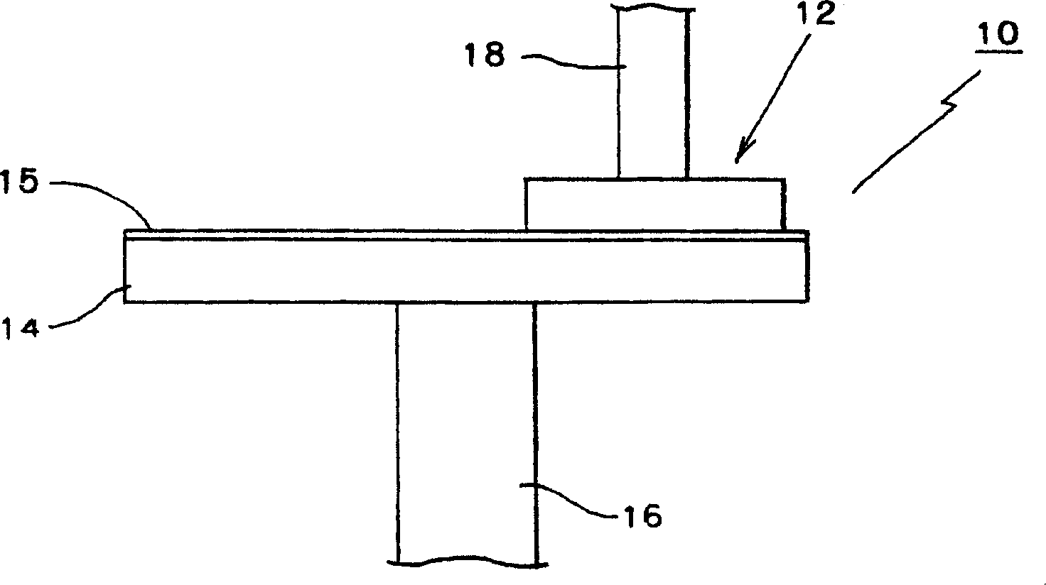
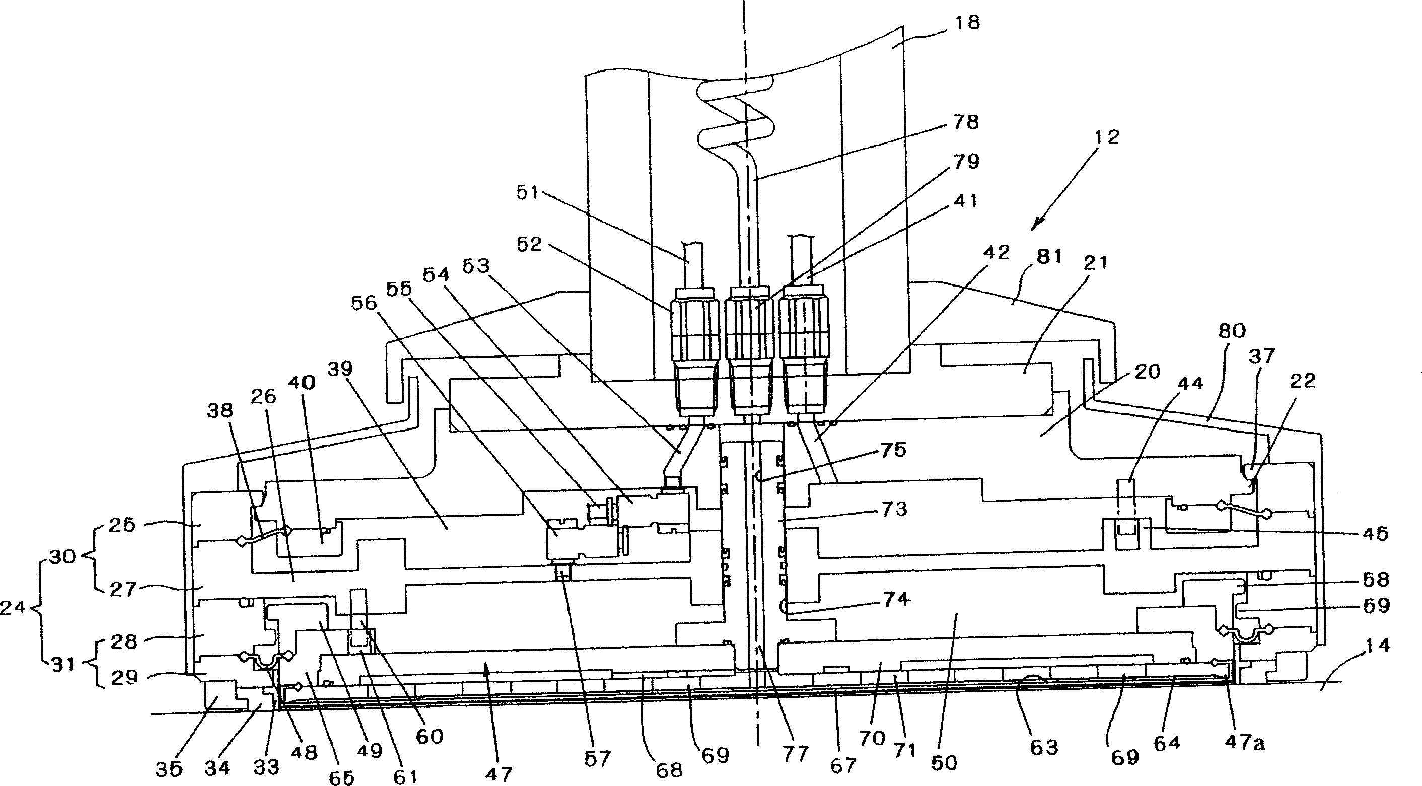
[0066] figure 1 is a schematic diagram of a polishing apparatus 10 related to the present invention, figure 2 is a sectional view of the fixed plate 12 of the first embodiment.

[0067] exist figure 1 In this case, a polishing pad 15 made of non-woven fabric, such as polyurethane, is attached to the upper surface of the polishing wheel 14, such as by an adhesive. The polishing wheel 14 rotates with the shaft 16 in a horizontal plane. Shaft 16 is rotated by a known drive mechanism (not shown).

[0068] The fixed disk 12 is connected to the lower end of the rotating shaft 18 . The rotary shaft 18 rotates about its axis and is moved up and down by a known mechanism (not shown). The fixed plate 12 is movable between a position on the upper side of the polishing wheel 14 and a position on the outer side of the polishing wheel 14 .

[0069] The...


PUM


Abstract

The polishing apparatus (10) is capable of precisely controlling polishing pressure, correctly positioning a press plate (47) and uniformly polishing a workpiece (W). In the polishing apparatus (10), a holding head comprises: first pressing means for introducing a pressurized fluid into a first fluid chamber (39) and pressing a main head section (24) downward; second pressing means for introducing a pressurized fluid into a second fluid chamber (50) and pressing a press plate (47) downward; and third pressing means for introducing a pressurized fluid into a third fluid chamber (64) and pressing the workpiece (W) downward. With this structure, the workpiece (W) is held on the lower side of an elastic sheet member (63), and the lower face of the workpiece (W) can be polished by a polishing plate (14).

Description

technical field [0001] The present invention relates to a polishing apparatus capable of uniformly polishing a workpiece such as a wafer. Background technique [0002] A wide variety of polishing equipment is known. [0003] Generally, a polishing apparatus includes: a polishing wheel having an upper surface on which a polishing pad is adhered; a fixing plate having a lower surface on which a workpiece is fixed to be pressed against the polishing pad; The polishing wheel is relatively moved relative to the fixed disc to polish the lower surface of the workpiece. [0004] A conventional polishing apparatus is disclosed in Japanese Patent Document No. 3158934. The polishing equipment includes a fixed plate, the fixed plate includes a head part of the main machine and a support located at the polishing head part, the support fixes the workpiece to be polished, and the retaining ring is located outside the support and arranged coaxially with it, the said support The retaining...

Claims


Application Information

Patent Timeline
Patent Type & Authority Applications(China)
IPC IPC(8): B24B37/005B24B37/30B24B37/32B24B49/16H01L21/304
CPCB24B49/16B24B37/30A63B71/141G10K15/04A63B2244/186
Inventor 宫小忠一岸田敬实
Owner FUJIKOSHI MACHINERY
Why Eureka
Try Eureka