
Return type satellite with high-level microgravity environment

A returnable satellite, microgravity technology, applied in the direction of artificial satellites, aerospace vehicle guidance devices, etc., can solve the problems of poor experimental results, large number of loads, and high power consumption, and achieve a good experimental environment and improved microgravity environment level. Effect

Active Publication Date: 2017-02-15
BEIJING INST OF SPACECRAFT SYST ENG
View PDF4 Cites 2 Cited by
  • Summary
  • Abstract
  • Description
  • Claims
  • Application Information

AI Technical Summary

Problems solved by technology

[0002] Space microgravity scientific experiments are usually expected to be carried out under the condition of complete weightlessness, and some experimental loads of returnable satellites can even be sensitive to less than 10 -6 g 0 The quasi-steady-state microgravity acceleration, but due to the existence of interference factors such as atmospheric resistance, tidal force, solar light pressure, attitude orbit control, and moving parts on the star, the satellite is subjected to certain non-conservative forces in orbit.
Moreover, due to the large number of payloads of space science experiment satellites, resulting in high power consumption, there are usually equipment with a large number of moving parts such as fans and fluid circuit systems on the satellite, coupled with disturbance sources such as attitude and orbit control actuators required by the satellite, It will inevitably affect the acquisition of a high-level microgravity environment. The level of the microgravity environment directly affects the experimental results. If the microgravity environment of the spacecraft is poor, the experimental results may be poor, and the experiment may even fail to achieve its scientific research goals. Influencing the results of space science experiments

Method used


Image

  • Return type satellite with high-level microgravity environment
  • Return type satellite with high-level microgravity environment
  • Return type satellite with high-level microgravity environment

Examples


Embodiment Construction

[0023] The present invention will be described in detail below with reference to the accompanying drawings and examples.

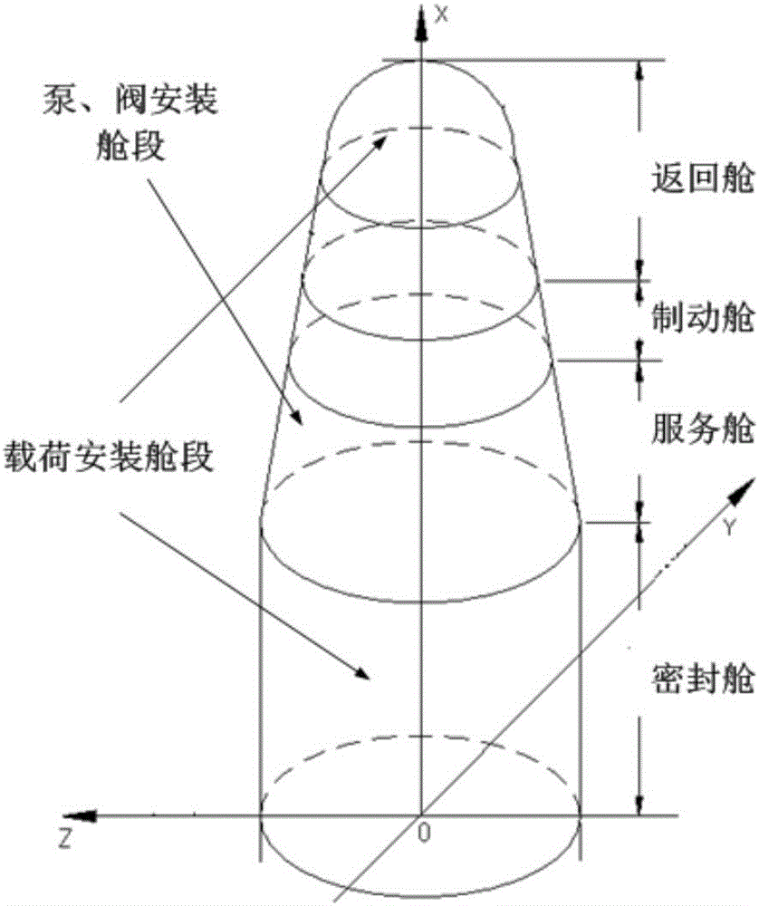
[0024] like Figure 5 As shown, the present invention provides a returnable satellite with a high-level microgravity environment, including a return module, a brake module, a service module and a sealed module;

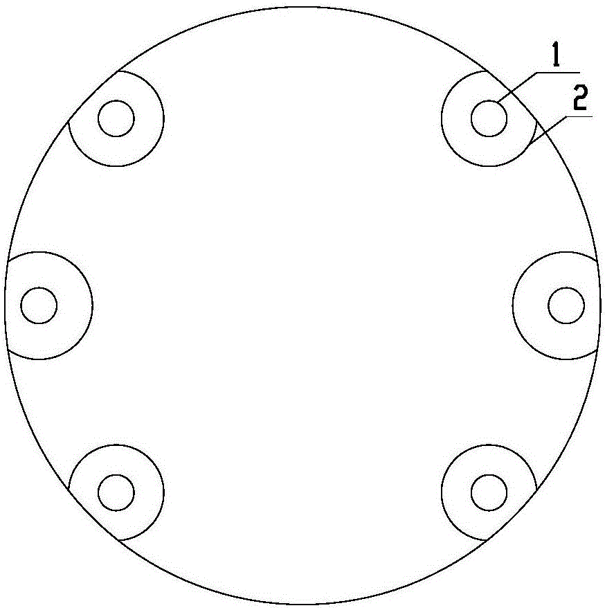
[0025] like Figure 1a and Figure 1b As shown, the lower cap at the bottom of the airtight cabin is a convex circular curved thin shell structure, which is a part of the spherical thin shell structure, and the material of the lower cap is aluminum alloy. The lower roof has a certain degree of flexibility. Due to the lower rigidity of the flexible lower roof, it can effectively isolate the high-frequency transient vibration generated by the thruster.

[0026] There are 6 installation holes for attitude control thrusters on the peripheral edge of the lower cap, such as Figure 1c As shown, the outer edge of each mounting hole is welded with an a...


PUM


Abstract

The invention discloses a return type satellite with a high-level microgravity environment. The return type satellite with the high-level microgravity environment comprises a return capsule, a brake capsule, a service capsule and a sealed capsule. A lower sealed roof of the bottom of the sealed capsule is of an outwards-convex circular curved thin-shell structure. Six attitude-control thruster mounting holes are formed in the peripheral edge of the lower sealed roof. An attitude-control thruster mounting support is welded to the outer edge of each mounting hole. The thrusting force of each attitude-control thruster is not larger than 2N. A constrained damping layer is arranged on the outer edge of each mounting support and formed by bonding a constraining layer and a damping layer together. Each constraining layer and the corresponding damping layer are circular rings with the same size. A micro-vibration source on the satellite is arranged in the service capsule. Microgravity experimental loads are arranged in the return capsule and the sealed capsule. At least five bolt connection links are arranged between the micro-vibration sources and the microgravity experimental loads. The return type satellite with the high-level microgravity environment focuses on solving the disturbance to the return type satellite microgravity link by the attitude-control thrusters and a fluid circuit system, and the instant micro-vibration and micro-vibration environment of the return type satellite are improved greatly.

Description

technical field [0001] The invention relates to the technical field of microgravity environment, in particular to a returnable satellite with a high-level microgravity environment. Background technique [0002] Space microgravity scientific experiments are usually expected to be carried out under the condition of complete weightlessness, and some experimental loads of returnable satellites can even be sensitive to less than 10 -6 g 0 The quasi-steady-state microgravity acceleration, but due to the existence of interference factors such as atmospheric resistance, tidal force, solar light pressure, attitude orbit control, and moving parts on the satellite, the satellite is subjected to certain non-conservative forces in orbit. Moreover, due to the large number of payloads of space science experiment satellites, resulting in high power consumption, there are usually equipment with a large number of moving parts such as fans and fluid circuit systems on the satellite, coupled w...

Claims


Application Information

Patent Timeline
Patent Type & Authority Applications(China)
IPC IPC(8): B64G1/10B64G1/26
CPCB64G1/10B64G1/26
Inventor 王颖张也弛刘欣邱家稳赵会光顾荃莹太萍李春华
Owner BEIJING INST OF SPACECRAFT SYST ENG
Learn More