A bin structure for a coating machine

A technology of coating machine and silo, applied in the field of coating machine, can solve the problems of improving the labor intensity of workers, burns, time-consuming and laborious, etc., and achieves the effects of improving precise control, preventing burns, and being convenient to use.

Active Publication Date: 2018-10-30
无锡光润真空科技有限公司
View PDF3 Cites 0 Cited by
  • Summary
  • Abstract
  • Description
  • Claims
  • Application Information

AI Technical Summary

Problems solved by technology

[0002] When the evaporating material in the silo of the coating machine is used up or needs to be cleaned, the traditional method is to manually pull out the silo and clean it. It is easy to cause burns to the laborers due to the high temperature of the silo when they are working

Method used


Image

  • A bin structure for a coating machine
  • A bin structure for a coating machine
  • A bin structure for a coating machine

Examples


Embodiment Construction

[0022] Specific embodiments of the present invention will be described below.

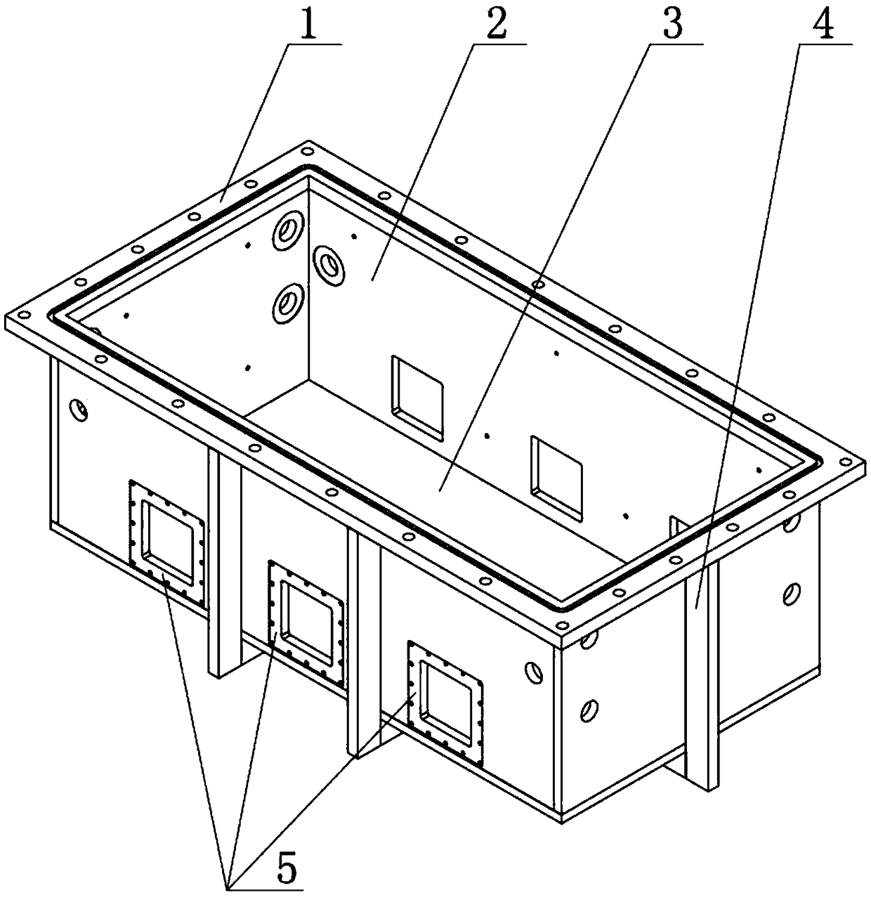
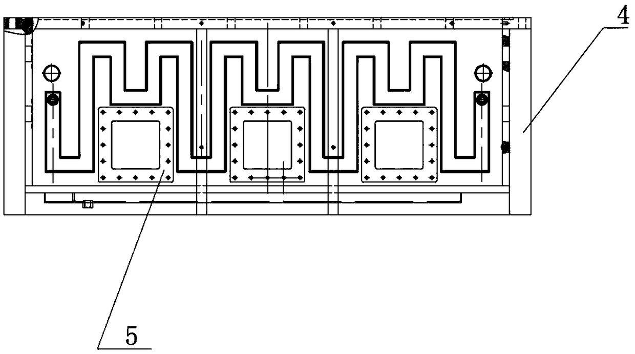
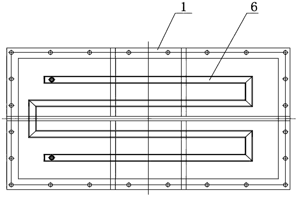
[0023] Such as Figure 5 , Image 6 As shown, a silo structure for a coating machine according to the present invention includes a silo body, the silo body is slidably connected with the guide rail 10 through rollers 13, and a plurality of cylinders 12 are arranged at the bottom of the silo body. The two ends of each are respectively provided with a first traction mechanism 8 and a second traction mechanism 9 for pulling the bin body on the guide rail for linear displacement. The above-mentioned cylinders 12 are respectively located at the front end and the rear end of the bottom of the silo body, and the cylinders 12 are used to lift the silo body and realize the communication between the silo body and the coating chamber 7 . Such as Figure 4 As shown, the above-mentioned first traction mechanism 8 and the second traction mechanism 9 both include a motor, a traction belt and a hook, the output...


PUM


Abstract

The invention relates to a stock bin structure used for a film coating machine. The stock bin structure comprises a stock bin body. The stock bin body is slidably connected with a guide rail through rolling wheels. A plurality of air cylinders are arranged at the bottom of the stock bin body. The two ends of the stock bin body are provided with a first hauling mechanism and a second hauling mechanism which are used for hauling the stock bin body to do linear displacement on the guide rail correspondingly. According to the stock bin structure used for the film coating machine, the structure is simple; using is convenient; the hauling mechanisms are arranged at the two ends of the stock bin body; linear displacement of the stock bin body on the guide rail is achieved through the rolling wheels, the guide rail and the hauling mechanisms, so that the labor intensity of workers is relieved, the situation that the labor personnel are scalded due to the fact that the temperature of a stock bin is too high during working is prevented, the safety performance is greatly improved, and the precise controllability of the stock bin structure is improved by arranging a photoelectric induction position switch.

Description

technical field [0001] The invention relates to the field of coating machines, in particular to a material bin structure for the coating machine. Background technique [0002] When the evaporating material in the silo of the coating machine is used up or needs to be cleaned, the traditional method is to manually pull out the silo and clean it. It is easy to cause the scalding of the laborers due to the high temperature of the silo when they are working. Contents of the invention [0003] In view of the above-mentioned existing problems, the applicant has carried out research and improvement, and provides a silo structure for a coating machine, which can realize the automatic entry and exit of the silo, reduce the labor intensity of the staff, and avoid the Excessive burns. [0004] The technical scheme adopted in the present invention is as follows: [0005] A silo structure for a coating machine, comprising a silo body, the silo body is slidingly connected to guide rai...

Claims


Application Information

Patent Timeline
Patent Type & Authority Patents(China)
IPC IPC(8): C23C14/24
CPCC23C14/243C23C14/246
Inventor 陈自新郑立冬朱海锋李伟
Owner 无锡光润真空科技有限公司
Why Eureka
Try Eureka