Supercharge Your Innovation With Domain-Expert AI Agents!

Prefabricated steel-plastic composite underground comprehensive pipe gallery

A steel-plastic composite and comprehensive pipe gallery technology, which is applied to underwater structures, artificial islands, and infrastructure engineering, can solve problems such as inconvenient maintenance for staff, messy pipeline laying, and increased failure risks, and achieve overall structural strength High, reduce construction difficulty, improve the effect of construction speed

Inactive Publication Date: 2018-10-26
杨省三
View PDF8 Cites 0 Cited by
  • Summary
  • Abstract
  • Description
  • Claims
  • Application Information

AI Technical Summary

Problems solved by technology

However, there are great defects in laying pipelines in this way, for example: 1. Once a fault occurs, it is not convenient for the staff to overhaul and often needs to be re-excavated
2. The pipeline laying inside the pipeline is messy, which increases the risk of failure
Large-scale multi-cabin pipe gallery, due to its large volume and heavy weight, the prefabricated assembly method is often restricted by transportation conditions or the capacity of on-site lifting equipment, making it difficult to implement
[0004] In addition, the existing comprehensive pipe gallery, whether it is made by excavation and cast-in-place method or prefabricated assembly method, is made of concrete, and its internal brackets are mainly fixed on the wall of the pipe gallery during installation. Brackets, this type of bracket is either directly embedded on the wall of the pipe gallery during the prefabrication or cast-in-place stage, or fixed on the wall of the pipe gallery by other fasteners after the construction of the pipe gallery is completed, but because the fasteners often need to penetrate into the pipe gallery On the wall, this will destroy the structure of the pipe gallery itself, especially the comprehensive pipe gallery with more brackets installed, which will be more affected

Method used


Image

  • Prefabricated steel-plastic composite underground comprehensive pipe gallery
  • Prefabricated steel-plastic composite underground comprehensive pipe gallery
  • Prefabricated steel-plastic composite underground comprehensive pipe gallery

Examples


Embodiment Construction

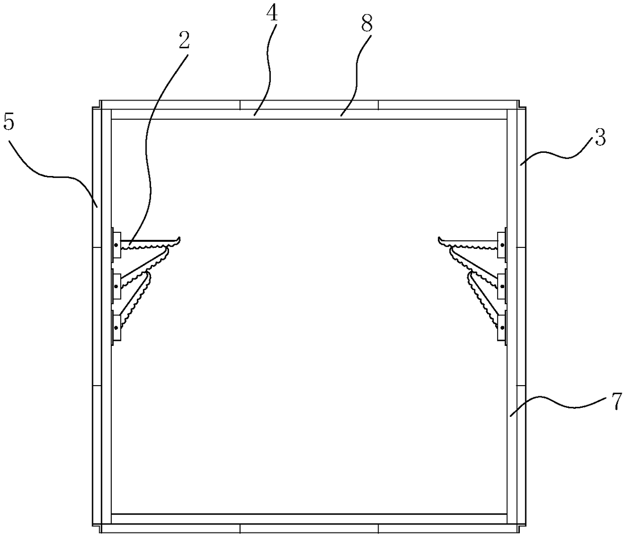
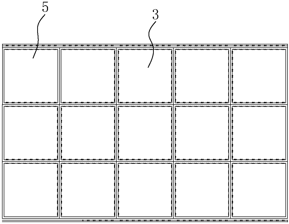
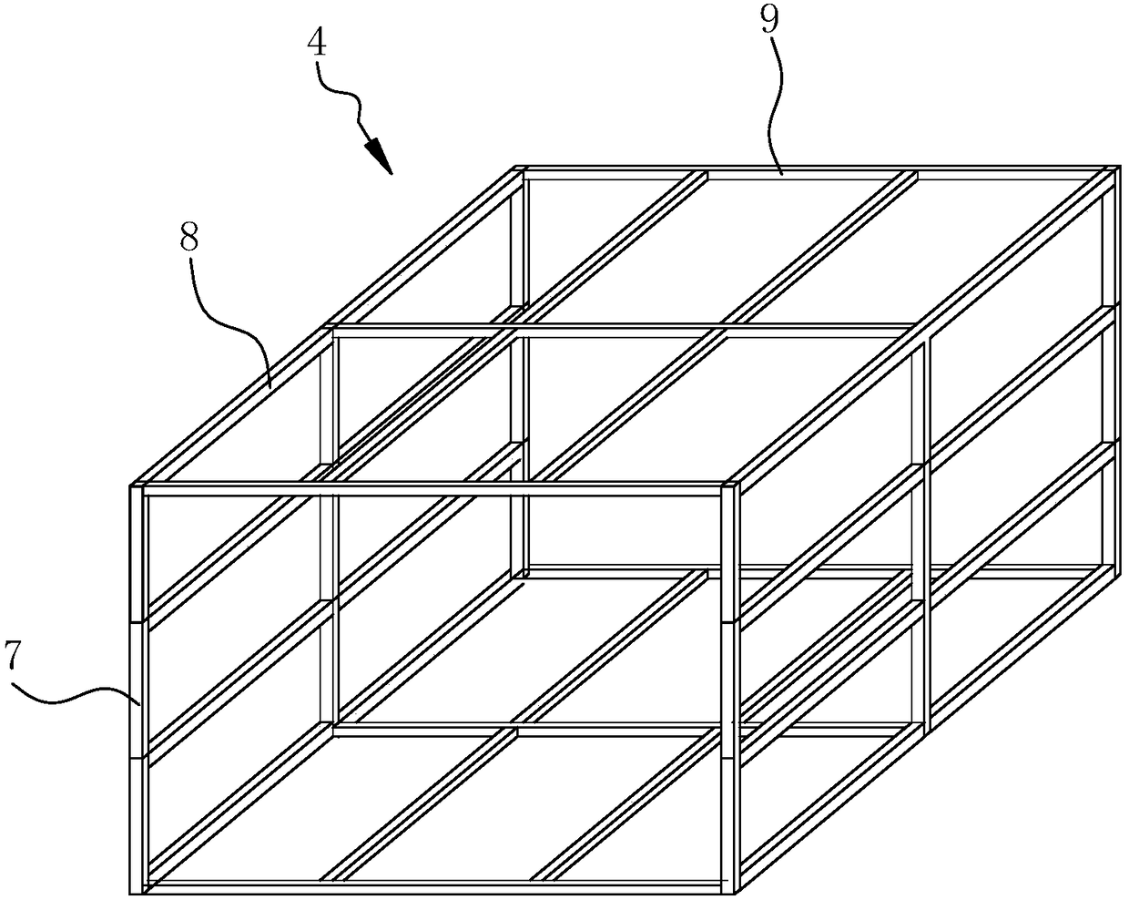
[0028] combine Figure 1-11 The prefabricated steel-plastic composite underground comprehensive pipe gallery shown includes the main body of the tunnel and several brackets 2 located inside the main body. The area without brackets 2 inside the main body of the tunnel can be used for laying drainage pipe networks, gas pipe networks, cable pipe networks, etc. The same support 2 can also be used for laying drainage pipe network, gas pipe network, cable pipe network and the like. The simplest bracket 2 is a plurality of horizontal rods located inside the main body, on which cables, wire ducts or various pipes can be placed, and the bracket 2 can also be a wire slot fixedly laid along the inner wall of the main body or other devices that play the same role structure. The main body includes a shell 3 and a skeleton 4 positioned on the inner wall of the shell 3, such as figure 2 As shown, the shell 3 is formed by splicing a plurality of square panels 5, and the square panels 5 hav...


PUM


Abstract

The invention relates to an underground pipe tunnel, in particular to an assembly type steel-plastic composite underground utility tunnel convenient to install and transport and high in structural strength. According to the technical scheme, the assembly type steel-plastic composite underground utility tunnel comprises a main tunnel body and a plurality of supports located inside the main tunnel body; the main tunnel body comprises a shell and a framework located on the inner wall of the shell, and the supports are located on the framework; the shell is formed by splicing a plurality of square panels; the framework is formed by connecting a plurality of steel bars; and the splicing gaps at joints of the panels correspond to the steel bars, and the steel bars are fixed to the panels through bolts. The assembly type steel-plastic composite underground utility tunnel has the advantages of being convenient to install and transport and high in structural strength.

Description

technical field [0001] The invention relates to an underground pipe gallery, in particular to an assembled steel-plastic composite underground comprehensive pipe gallery. Background technique [0002] With the rapid expansion of demand for electricity, communications, water supply, and gas in cities across the country in the past ten years, the laying of power transmission cables, communication cables, water supply pipes, sewer pipes, and gas pipes in urban infrastructure construction has shown a blowout growth. Laying various pipelines directly on the ground will take up a lot of land resources. Especially in cities with serious shortage of land resources, this contradiction is particularly prominent. At present, the conventional pipeline laying method is to pre-bury the pipeline underground, and then lay the pipeline along the pipeline. But there are great defects in laying pipelines in this way, for example: 1. In case of failure, it is not convenient for staff to carry...

Claims


Application Information

Patent Timeline
Patent Type & Authority Patents(China)
IPC IPC(8): E02D29/045C08L67/06C08L25/06C08L33/12C08K13/04C08K7/14C08K3/26C08K3/22C08K5/098C08K3/30
CPCC08L67/06C08L2205/03E02D29/045C08L25/06C08L33/12C08K13/04C08K7/14C08K2003/265C08K3/26C08K2003/2244C08K2003/222C08K5/098C08K2003/3009
Inventor 杨省三
Owner 杨省三
Features
  • R&D
  • Intellectual Property
  • Life Sciences
  • Materials
  • Tech Scout
  • Unparalleled Data Quality
  • Higher Quality Content
  • 60% Fewer Hallucinations
Learn More