Real-time working condition diagnostic method for belt type oil pumping unit

A technology of real-time working conditions and diagnostic methods, applied in construction and other directions, can solve the problems of insufficient popularization and utilization of the advantages of electrical power diagrams, and limited application of electrical power diagrams.

Active Publication Date: 2017-02-15
CHINA PETROLEUM & CHEM CORP +1
View PDF7 Cites 12 Cited by
  • Summary
  • Abstract
  • Description
  • Claims
  • Application Information

AI Technical Summary

Problems solved by technology

However, at present, the application of electric power diagrams in oil fields is relatively limited, and the advantages of electric power diagrams have not been fully popularized and utilized, especially in the diagnosis of oil well conditions

Method used


Image

  • Real-time working condition diagnostic method for belt type oil pumping unit
  • Real-time working condition diagnostic method for belt type oil pumping unit
  • Real-time working condition diagnostic method for belt type oil pumping unit

Examples


Embodiment 1

[0111] The method for diagnosing real-time working conditions of the belt pumping unit of this embodiment includes the following steps:

[0112] 1) Analyze and calculate the suspension point motion model of the belt pumping unit, specifically:

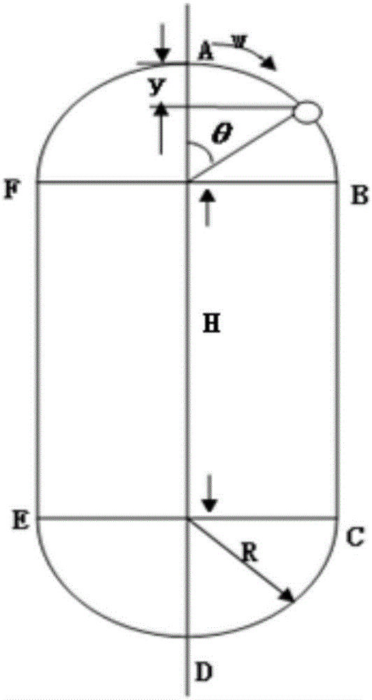
[0113] The driving sprocket of the pumping unit rotates clockwise at an angular velocity ω, and the direction of movement of the suspension point of the pumping unit is opposite to that of the shuttle frame; figure 2 As shown, A—D is the upstroke, D—A is the downstroke; when the suspension point is at the bottom dead center as the starting point, the suspension point displacement S in the harmonic motion section w , Speed ​​V w , And acceleration a w They are:

[0114] S w =R(1-cosθ) (1);

[0115] V w =Rωsinθ (2);

[0116] a w =Rω 2 cosθ (3);

[0117] From the stroke and stroke times of the pumping unit, the angular velocity ω of the driving sprocket can be deduced as:

[0118]

[0119] Where, S w Is the displacement of the shuttle rack, m; V w I...

example

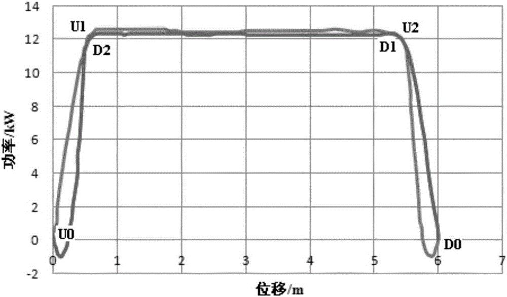
[0194] Taking a well on site as an example, the pumping unit parameters and oil well production parameters of the well are shown in Table 1, and the measured electrical work diagram is shown in Table 1. Figure 15 Shown.

[0195] Table 1 Field oil well parameter table

[0196] Pumping unit model Balance weight (kN) Stroke (m)Stroke times (min -1 )

Sprocket radius (m) 600 belt pumping unit604.82.10.46

[0197] The real-time operating condition diagnosis method of the belt pumping unit of Example 1 is used for diagnosis.

[0198] Combined with the measured electrical work diagram (such as Figure 15 (Shown), the electric power of the downstroke has two platforms-the low platform at the beginning of the downstroke corresponds to the empty section of the pump, and then the high platform corresponding to the liquid section of the pump. The change from the low platform to the high platform is approximately an oblique straight line.

[0199] Typical characteristic value calculation (so...


PUM


Abstract

The invention discloses a real-time working condition diagnostic method for a belt type oil pumping unit. The real-time working condition diagnostic method comprises the following steps: 1, analyzing and calculating a suspension point movement model of the belt type oil pumping unit so as to obtain a relationship between the speed and the displacement of a suspension point, and establishing a power and suspension point load conversion model; 2, according to the power and suspension point load conversion model, converting a typical indicating diagram to a motor power diagram curvature with displacement as an X coordinate and motor power as a Y-coordinate, and establishing a motor power diagram working condition diagnostic model; and 3, collecting the real-time motor power diagram of the belt type oil pumping unit, comparing the real-time motor power diagram with the motor power diagram working condition diagnostic model, and realizing real-time working condition diagnosis. The method enhances the real-time monitoring and working condition diagnosis of the belt type oil pumping unit and increases the production efficiency of the belt type oil pumping unit. The method can extract typical characteristic values from the motor power diagram working condition diagnostic model, facilitates the comparison and working condition judgment of the real-time motor power diagram, easily realizes automatic diagnosis, is high in accuracy and high in speed, and helps enhancing the intelligent management of an oil field.

Description

Technical field [0001] The invention belongs to the technical field of oil extraction equipment working condition diagnosis, and particularly relates to a real-time working condition diagnosis method of a belt pumping unit. Background technique [0002] The belt pumping unit is a long-stroke, slow-stroke, and purely mechanically driven beamless pumping unit. Due to its good oil extraction process performance and reliable mechanical properties, it has been widely used in oil fields and created Better economic benefits. The belt pumping unit has the following characteristics: heavy load, long stroke, low stroke; the whole machine is 100% mechanical transmission, folding structure, has the characteristics of simple operation, convenient installation and transportation, and safe operation; high reliability and operation of the hand brake Convenient; good energy-saving effect; simple management and convenient maintenance; belt conveyor has an electromagnetic automatic brake protectio...

Claims


Application Information

Patent Timeline
Patent Type & Authority Applications(China)
IPC IPC(8): E21B47/008
CPCE21B47/008
Inventor 张朋肖良飞胡英才陈德春杨康敏孟红霞杨冰李奇
Owner CHINA PETROLEUM & CHEM CORP
Why Eureka
Try Eureka