
Double-jet-pump structure and jet head

A jet pump and jet head technology, applied to engine components, liquid fuel feeders, machines/engines, etc., can solve the problems of increased parts cost, complex structure, filter area limitation, etc., and achieve compact structure and reduced lateral size Effect

Active Publication Date: 2017-02-15
UNITED AUTOMOTIVE ELECTRONICS SYST
View PDF4 Cites 0 Cited by
  • Summary
  • Abstract
  • Description
  • Claims
  • Application Information

AI Technical Summary

Problems solved by technology

This single dual-jet pump assembly not only has a complicated structure, which increases the cost of a part, but also takes up a large space in the oil storage tank, causing the structural layout of other parts (such as fine filters) to be very limited.
[0004] figure 1 Shown is the existing dual-jet pump oil pump bracket with dual active drive structure. Due to the existence of the dual-jet pump assembly, the fine filter 2 cannot be made too large when the internal space of the oil storage barrel 1 is certain. The area is very limited and cannot be arranged as a separately replaceable fine filter 2 structure

Method used


Image

  • Double-jet-pump structure and jet head
  • Double-jet-pump structure and jet head
  • Double-jet-pump structure and jet head

Examples


Embodiment 1

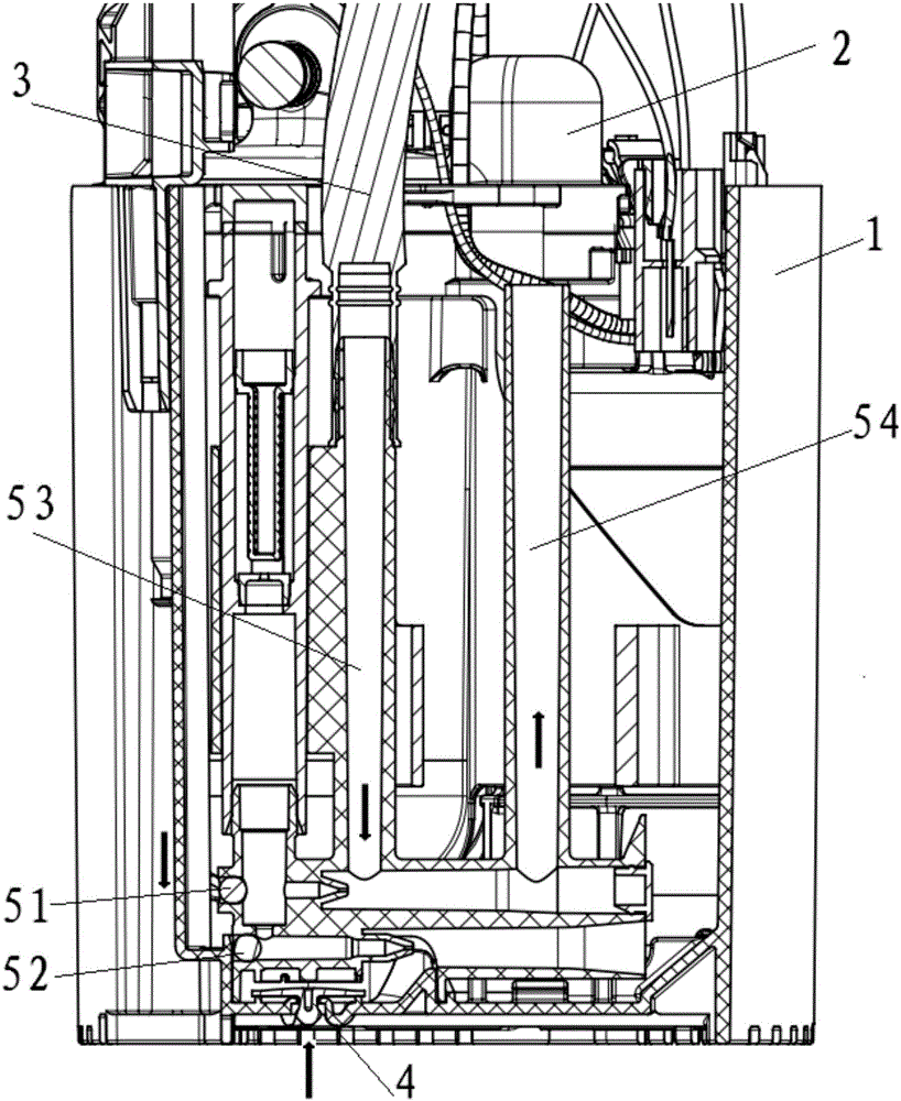
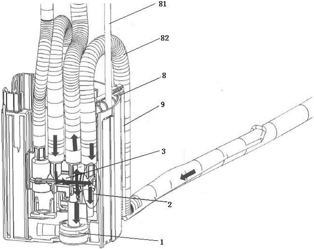
[0083] The double jet pump structure is used to place in the oil barrel, and the oil barrel is placed in the main oil tank; if figure 2 , image 3 , Figure 4 , Figure 5 and Figure 6 As shown, the dual jet pump structure includes a fluid pipe assembly 3, a first jet pump 1, and a second jet pump 2;

[0084] The fluid pipe assembly 3 includes a first pipeline 32, a second pipeline 33, and an oil suction pipe 35;

[0085] The first pipeline 32 is connected to the first injection pump 1;

[0086] The second pipeline 33 is connected to the second injection pump 2;

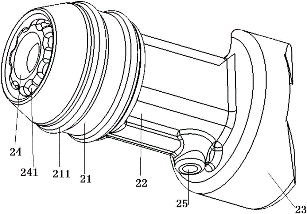
[0087] The second injection pump 2 includes an injection head, and the injection head is a head 21, a body 22, and a tail 23 in sequence along the axial direction;

[0088] The lumens of the head 21 and the body 22 are both tubular and communicated;

[0089] On the outer wall of the body 22, there is a spray hole 25 which communicates with the inner cavity of the body 22 along the radial direction;

[0090] ...

Embodiment 2

[0098] Based on the dual-jet pump structure of Embodiment 1, the fluid pipe assembly 3 further includes a third pipeline 31 and a fourth pipeline 34;

[0099] The third pipeline 31 is used to send oil out of the fuel tank;

[0100] The fourth pipeline 34 is used for the oil pump to supply oil to the fluid pipe assembly 3 .

[0101] Preferably, the axes of the first pipeline 32, the third pipeline 33, the fourth pipeline 34 and the oil suction pipe 35 are longitudinal;

[0102] The axis of the second pipeline 33 is transverse.

[0103] Preferably, the first pipeline 32 , the third pipeline 33 and the fourth pipeline 34 are on the same side of the second pipeline 33 , and the oil suction pipe 35 is on the opposite side of the second pipeline 33 .

[0104] Preferably, the first pipeline 32 faces downward, and the third pipeline 33 and the fourth pipeline 34 face upward.

[0105] In the double jet pump structure of Embodiment 2, the jet head of the second jet pump 2 is arranged...

Embodiment 3

[0107] Based on the dual-jet pump structure of Embodiment 1, such as image 3 , Figure 4 , Figure 5 As shown, the injection head of the second injection pump 2 also includes a filter 24;

[0108] The inner diameter of the nozzle head 21 is greater than the inner diameter of the body 22;

[0109] The filter 24 is cylindrical, and there are one or more grooves 241 on the cylindrical surface of the filter 24 in the axial direction;

[0110] The filter 24 is installed and fixed in the spray head head 21 .

[0111] Preferably, the inner cavity of the nozzle head 21 is cylindrical;

[0112] The filter 24 is cylindrical.

[0113] Preferably, the cross section of each groove 241 in the axial direction of the cylinder of the filter 24 is smaller than the cross section of the injection hole 25 of the second injection pump 2 .

[0114] Preferably, the cylindrical surface of the filter 24 is installed and fixed together with the inner wall of the spray head head 21 through interfe...


PUM


Abstract

The invention discloses a double-jet-pump structure. The double-jet-pump structure comprises a fluid pipe assembly, a first jet pump and a second jet pump, wherein the fluid pipe assembly comprises a first pipeline, a second pipeline and an oil sucking pipe; the first pipeline is connected to the first jet pump; the second pipeline is connected to the second jet pump; the second jet pump comprises a jet head, and the jet head is sequentially provided with a head part, a main body and a tail part in the axial direction; inner cavities of the head part and the main body are both tubular and communicate with each other; a jet hole communicating with the inner cavity of the main body is formed in the outer wall of the main body in a radial direction; and the head of the jet head is embedded in the second pipeline, the outer wall of the head is hermetically connected with the second pipeline, fuel oil is fed from the head and sprayed out from the jet hole in the main body, the oil inlet direction is perpendicular with the oil outlet direction, and a negative pressure zone formed by the fuel oil sprayed by the jet hole is located in the oil sucking pipe. The invention further discloses a jet head. The structure of the double-jet-pump structure is compact, and the double-jet-pump structure can be arranged in a limited oil storing barrel space.

Description

technical field [0001] The invention relates to an automobile oil pump, in particular to a double-jet pump structure and a spray head. Background technique [0002] At present, the oil pump bracket assembly used in the saddle type oil tank, because of the extra one-way remote oil-absorbing structure, the oil storage tank is generally larger, so that there is enough space to arrange the two-way oil-absorbing structure, but when the oil tank mouth is small, the large oil storage tank The barrel cannot be loaded into the fuel tank, and the vehicle factory uses a uniform fuel tank, the fuel tank opening cannot be enlarged, and only a smaller oil storage barrel can be used, so it is necessary to arrange a two-way oil suction structure in the smaller oil storage barrel space , in order to meet the needs of saddle-type fuel tanks with smaller fuel tank openings. [0003] In the current gasoline fuel system, the dual-injection pump oil pump support assembly is generally a dual-acti...

Claims


Application Information

Patent Timeline
IPC IPC(8): F02M37/04F02M37/22
CPCF02M37/04F02M37/22
Inventor 徐巍巍
Owner UNITED AUTOMOTIVE ELECTRONICS SYST
Features
  • Generate Ideas
  • Intellectual Property
  • Life Sciences
  • Materials
  • Tech Scout
  • Unparalleled Data Quality
  • Higher Quality Content
  • 60% Fewer Hallucinations
Learn More