Working method of temperature control hydraulic heat exchange system with ball pressure release valve and for hydraulic bypass

A technology of heat exchange system and working method, applied in the direction of fluid pressure actuating system components, safety valve, balance valve, etc., can solve the problems of pressure increase, flow unbalance, easy damage of radiator, scrapping, etc., so that it is not easy to damage , the effect of high reliability

Active Publication Date: 2017-02-15
江苏金荣森制冷科技有限公司
View PDF8 Cites 3 Cited by
  • Summary
  • Abstract
  • Description
  • Claims
  • Application Information

AI Technical Summary

Problems solved by technology

It has a small liquid storage capacity and no buffer. In the case of large temperature difference, low temperature environment, unbalanced flow, liquid with a certain viscosity, and fluid with impact force, the pressure inside the heat dissipation channel of the radiator will also increase. , especially in the case of impact force and relatively high viscosity fluid, due to the resistance of the fluid inside the channel, the fluid cannot quickly pass through the inside of the radiator channel, so that the pressure increases, exceeding the maximum operating pressure of the radiator, and the radiator is very Easily damaged and scrapped

Method used


Image

  • Working method of temperature control hydraulic heat exchange system with ball pressure release valve and for hydraulic bypass
  • Working method of temperature control hydraulic heat exchange system with ball pressure release valve and for hydraulic bypass
  • Working method of temperature control hydraulic heat exchange system with ball pressure release valve and for hydraulic bypass

Examples


Embodiment 1

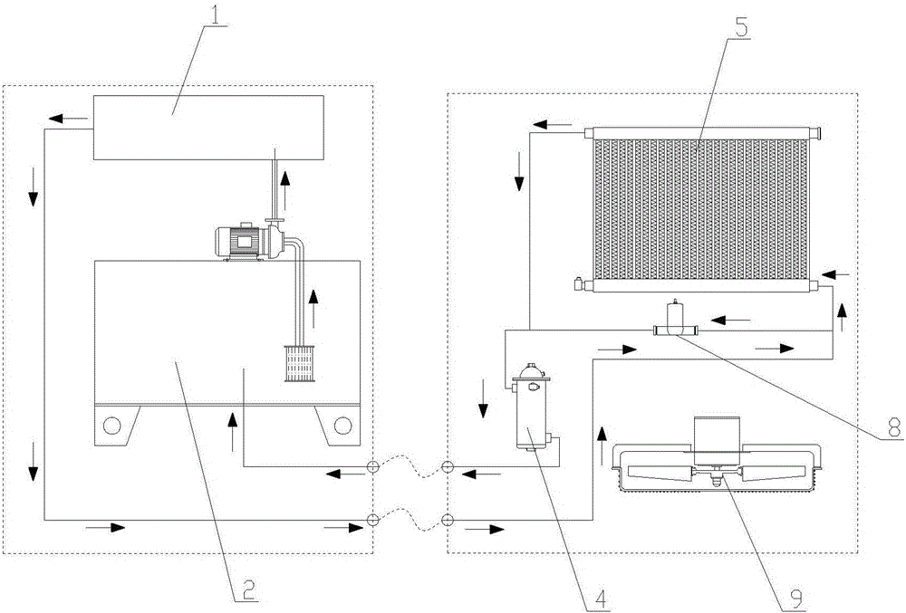
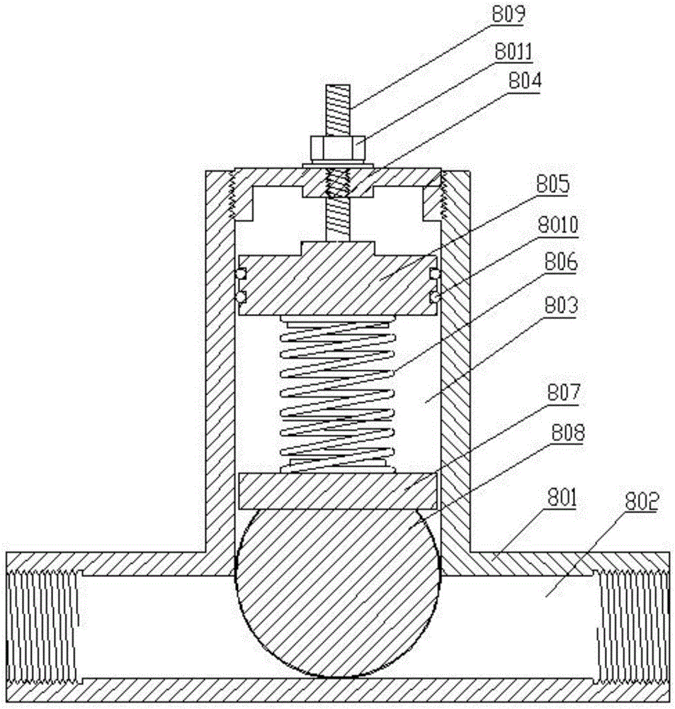
[0041] Example 1. When the liquid flows from left to right and the main hydraulic circuit is blocked, the pressure at the left end of the ball pressure relief valve is greater than the pressure at the right end, because the pressure in the fluid channel on the left side of the ball is greater than the pressure in the fluid channel on the right side of the ball Pressure, the fluid pushes the ball upwards, the bottom of the ball forms a space for the fluid to move, the fluid moves from left to right in the fluid channel, so as to achieve the purpose of pressure relief, until the pressure on the left and right sides of the ball is equal, the ball returns to its original position position, the main hydraulic circuit returns unobstructed.

Embodiment 2

[0042] Example 2. When the liquid flows from left to right and the hydraulic main road is blocked, the pressure at the right end of the ball relief valve is greater than the pressure at the left end, because the pressure in the fluid channel on the right side of the ball is greater than the pressure in the fluid channel on the left side of the ball Pressure, the fluid pushes the ball upwards, the bottom of the ball forms a space for the fluid to move, the fluid moves from right to left in the fluid channel, so as to achieve the purpose of pressure relief, until the pressure on the left and right sides of the ball is equal, the ball returns to its original position position, the main hydraulic circuit returns unobstructed.


PUM


Abstract

The invention relates to a working method of a temperature control hydraulic heat exchange system with a ball pressure release valve and for a hydraulic bypass. In the initial operation stage of an equipment heating source, the liquid temperature is lower than 35 DEG C, a radiating fan is not turned on, a tubular heater is started, the oil temperature is increased to within the range of 35-55 DEG C, then the tubular heater is turned off, and after the equipment heating source is operated for some time, the radiating fan is turned on when a temperature sensor detects that the temperature is higher than 60 DEG C; and when a radiator is blocked or the internal pressure of the radiator is too high, the pressure on one side of the ball pressure release valve is higher than the pressure on the other side of the ball pressure release valve, due to the fact that the pressure in a fluid flow channel on the high-pressure side of a ball is higher than the pressure in the fluid flow channel on the low-pressure side of the ball, fluid pushes the ball to move upwards and moves in the fluid flow channel from the high-pressure side to the low-pressure side, the purpose of pressure release is achieved, and a main hydraulic path is unobstructed again until the pressures on the two sides of the ball are equal. The working method has the advantages that the reliability is high, damage is not prone to occurring, and the stable operation of the system is ensured.

Description

technical field [0001] The invention relates to a working method of a temperature-controlled hydraulic heat exchange system with a hydraulic bypass of a ball-type pressure relief valve. Background technique [0002] As we all know, the best oil temperature of the hydraulic system is between 35 and 55 degrees Celsius. Once the temperature rises above 60 degrees Celsius, the system of the hydraulic system will drop significantly, and equipment failures will continue to occur, resulting in a serious decline in the stability of the equipment. There is no guarantee that the machine will function properly. Especially in the midsummer season, the oil temperature is too high, and even the machinery and equipment are often shut down. [0003] Therefore, the stability of the hydraulic heat exchange system directly affects the working status of the machinery and equipment. When the liquid pressure in the traditional hydraulic heat exchange system is too high, it will directly lead to ...

Claims


Application Information

Patent Timeline
IPC IPC(8): F15B21/04F16K17/06
CPCF15B21/042F15B2211/62F16K17/06
Inventor 黄晓军
Owner 江苏金荣森制冷科技有限公司
Why Eureka
Try Eureka