Sintering cooler and dynamic sealing equipment thereof

A technology of sintering cooling machine and dynamic sealing, which is applied in lighting and heating equipment, treatment of discharged materials, furnaces, etc. It can solve the problems of poor sealing effect, reduce air leakage rate, good wear resistance, and increase boiler power generation Effect

Active Publication Date: 2017-02-15
ANHUI UNIVERSITY OF TECHNOLOGY
View PDF10 Cites 0 Cited by
  • Summary
  • Abstract
  • Description
  • Claims
  • Application Information

AI Technical Summary

Problems solved by technology

[0007] The purpose of the present invention is to overcome the shortage of poor sealing effect between the cooling bed trolley and the fume hood in the prior art, provide a sintering cooler and its dynamic sealing equipment, and improve the sealing effect between the cooling bed trolley and the fume hood. The sealing effect

Method used


Image

  • Sintering cooler and dynamic sealing equipment thereof
  • Sintering cooler and dynamic sealing equipment thereof
  • Sintering cooler and dynamic sealing equipment thereof

Examples


Embodiment 1

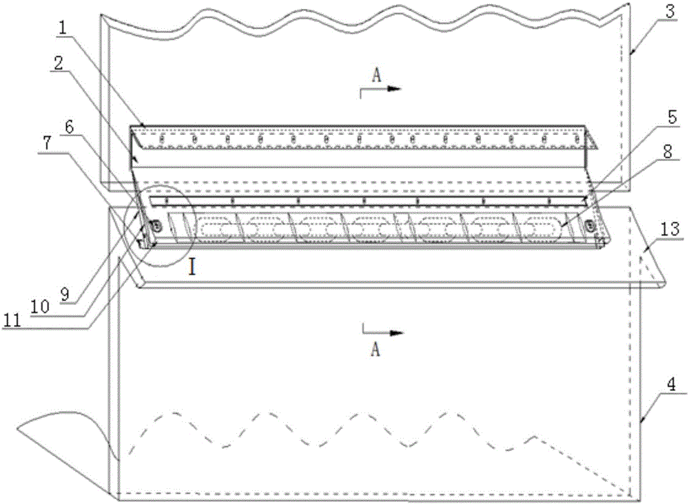
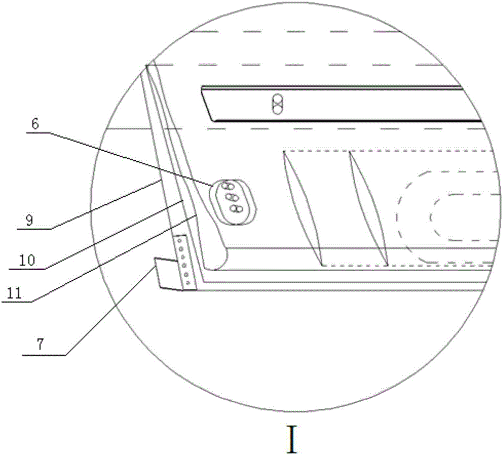
[0064] The seal between the cooling bed trolley and the smoke hood in the traditional sintering cooler is made of a fiberboard with a certain strength, and one side of the fiberboard is fixed on the fume hood, and the dynamic friction between the fiberboard and the top of the cooling bed trolley is used. Sealing is achieved, but the sealing effect of this line sealing method is relatively poor, and due to the large temperature difference between the two sides of the fiberboard, after periodic thermal expansion and contraction, the strength of the fiberboard itself is attenuated, and the deformed fiberboard exerts pressure on the top of the cooling bed trolley. The gap between the two is getting bigger and bigger, and the air leakage rate is gradually increasing; moreover, due to the wear of the track, there is a misalignment between adjacent cooling bed trolleys on the track, which will make the cooling bed trolley Scratching with the fiberboard during exercise will cause the f...

Embodiment 2

[0068] refer to Figure 1~4 , the sintered cooling machine of the present embodiment, its structure is basically the same as embodiment 1, further:

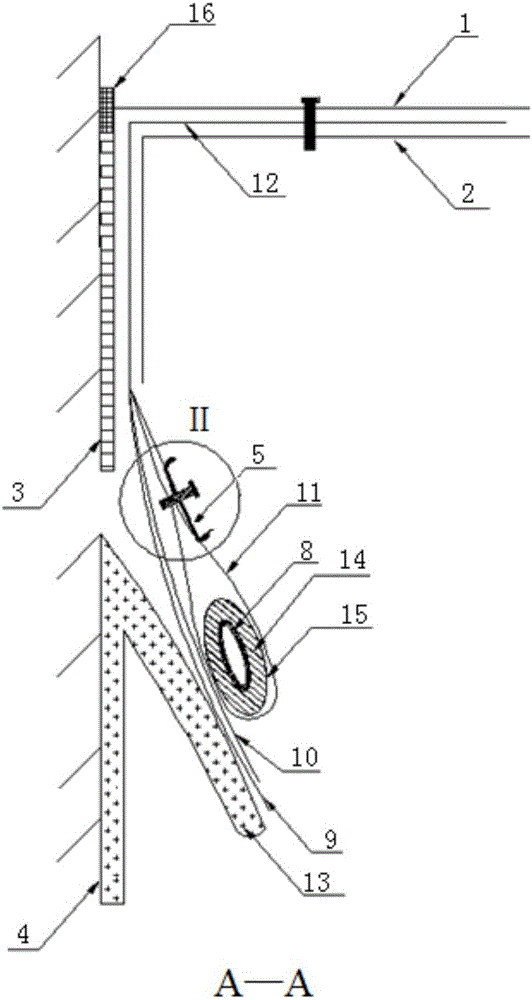
[0069] Wherein, the dynamic sealing device includes: a heat-resistant sealing layer 12 whose upper end is fixed on the side of the hood 3 , and a counterweight 8 is connected to the lower end of the heat-resistant sealing layer 12 .

[0070] In this embodiment, the heat-resistant sealing layer 12 can play a good sealing role, and can withstand higher ambient temperature during work; the counterweight 8 is connected to the lower end of the heat-resistant sealing layer 12, so that the heat-resistant sealing layer 12 The lower end is compressed on the cooling trolley 4 under the gravity of the counterweight 8 to realize the compression and sealing effect.

Embodiment 3

[0072] refer to Figure 1~4 , the sintered cooling machine of the present embodiment, its structure is basically the same as that of embodiment 2, further:

[0073] The heat-resistant sealing layer 12 is made of flexible materials; the upper part of the cooling trolley 4 is provided with an inclined plate 13 inclined downward, and the lower end of the heat-resistant sealing layer 12 is pressed against the surface of the inclined plate 13 under the gravity of the counterweight 8 .

[0074] In this embodiment, the upper part of the cooling trolley 4 is provided with an inclined plate 13 inclined downward, and the lower end of the heat-resistant sealing layer 12 is pressed against the surface of the inclined plate 13 under the gravity of the counterweight 8, wherein the inclined plate 13 is inclined downward. The inclined plate 13 can be arranged on the inner side of the upper part of the cooling trolley 4, and can also be arranged on the outer side of the upper part of the cool...


PUM


Abstract

The invention discloses a sintering cooler and dynamic sealing equipment thereof and belongs to the field of sintering equipment in the steel metallurgical industry. The sintering cooler and the dynamic sealing equipment thereof aim at overcoming the defect that the sealing effect between cooling bed trolleys and smoke hoods is poor in the prior art. The sintering cooler comprises multiple sections of cooling trolleys loading sinter and multiple smoke hoods arranged above the multiple sections of cooling trolleys. The sintering cooler further comprises dynamic sealing devices used for sealing the gaps between the cooling trolleys and the smoke hoods. The upper ends of the dynamic sealing devices are fixed to the side faces of the smoke hoods, and the lower ends of the dynamic sealing devices are suspended downwards and press the cooling trolleys under the action of gravity. According to the sintering cooler and the dynamic sealing equipment thereof, the sealing effect between the cooling trolleys and the smoke hoods is improved.

Description

technical field [0001] The invention belongs to the field of sintering equipment in the iron and steel metallurgy industry, and more specifically relates to a sintering cooling machine and dynamic sealing equipment thereof. Background technique [0002] In steel production, sintering production is one of the important processes, which provides high-quality raw materials for blast furnace ironmaking. After the sintering is completed, when the cooling bed trolley carries the hot sintered clinker and moves directional on the track, the bellows blows air upwards at the bottom of the cooling bed trolley, and the cold air passes through the sintering material layer to cool the sintering material. After being heated, it is sent to In this way, the sensible heat in the sintered material layer can be recovered to improve energy utilization efficiency. In order to increase the hot air temperature as much as possible, it is necessary to ensure that there is a reliable seal between the...

Claims


Application Information

Patent Timeline
Patent Type & Authority Applications(China)
IPC IPC(8): F27D15/02F27D99/00
CPCF27D15/0206F27D99/0076F27M2003/04
Inventor 王恒达陈光包向军李显宝冯森侯璞明
Owner ANHUI UNIVERSITY OF TECHNOLOGY
Why Eureka
Try Eureka