
Controllable coolant pump with a filter disc, filter disc, and the production thereof

A coolant pump and filter technology, applied in the cooling of the engine, the components of the pumping device for elastic fluid, pump control, etc., can solve the problem of damage to the coolant pump adjustment behavior, to maintain dimensional stability, Improvement of dynamic sealing, effect of reducing leakage flow

Inactive Publication Date: 2020-12-22
尼得科GPM有限公司
View PDF8 Cites 0 Cited by
  • Summary
  • Abstract
  • Description
  • Claims
  • Application Information

AI Technical Summary

Problems solved by technology

In addition, the regulation behavior during the start and stop of the coolant pump is impaired due to the leakage flow on the hydraulic control circuit

Method used


Image

  • Controllable coolant pump with a filter disc, filter disc, and the production thereof
  • Controllable coolant pump with a filter disc, filter disc, and the production thereof

Examples


Embodiment Construction

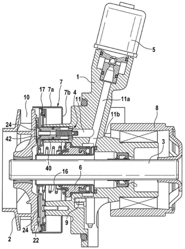
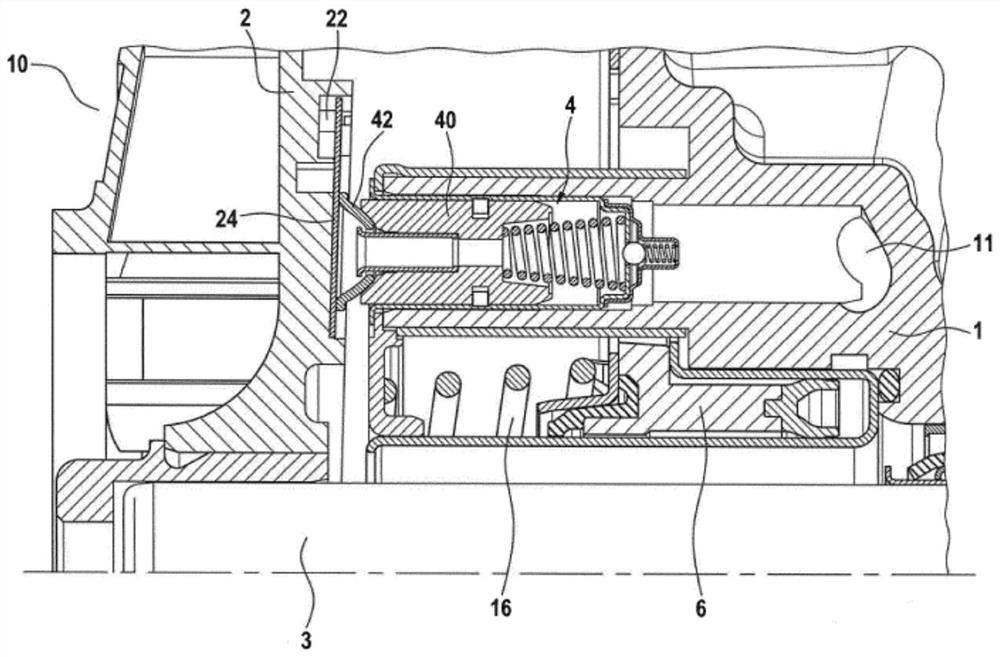
[0034] reference here figure 1 and 2 Describe the structure of the coolant pump.

[0035] like figure 1 The coolant pump shown comprises a pump housing 1 and a pump shaft 3 rotatably mounted therein, which has a pulley 8 which is driven by a belt drive of a not shown internal combustion engine. Arranged for co-rotation at the free end of the pump shaft 3 is an impeller 2 , which is integrated in a pump chamber 10 in the flow region of the coolant circuit of the internal combustion engine in order to achieve a volume flow of the coolant. Coolant is sucked into the central area of ​​the impeller 2 through an axial inlet (not shown) of the pump chamber 10 and discharged through a radial outlet (not shown) of the pump chamber 10 opposite the peripheral area of ​​the impeller 2 .

[0036] The flow area of ​​the impeller 2 can be covered in a variably manner by means of an adjusting slide 7 which has a cylindrical section 7 a arranged coaxially with the pump shaft 3 and a rear e...


PUM

PropertyMeasurementUnit
diameteraaaaaaaaaa
thicknessaaaaaaaaaa

Abstract

The present invention provides a controllable coolant pump with a filter disc, a filter disc, and the production thereof. In a controllable coolant pump for conveying a coolant for an internal combustion engine, a conveying stream of the coolant can be limited by way of a control slide (7) which is actuated by way of a hydraulic actuator (6) in a hydraulic control circuit (11), wherein the hydraulic control circuit (11) is fed with the coolant from the conveying stream, and comprises an axial piston pump (4) and a proportional valve (5) for generating and controlling a pressure to the hydraulic actuator (6). A sliding pad (42) which is arranged towards a suction side of the axial piston pump (4) surrounds an inlet of the axial piston pump (4), and a filter disc (24) for filtering the coolant before an inlet into the hydraulic control circuit (11) is in sliding contact with the sliding pad (42), with the result that coolant is sucked from the pump chamber (10) through the filter disc (24) and the sliding pad (42) into the axial piston pump (4) while a rotational movement of the filter disc (24) is transferred into a lifting movement of the axial piston pump (4). The filter disc (24)consists of a ceramic material.

Description

technical field [0001] The present invention relates to an adjustable coolant pump with an improved filter disc, to an improved filter disc for a corresponding adjustable coolant pump, and to a method of manufacturing the improved filter disc. Background technique [0002] The prior art discloses mechanically driven coolant pumps in which, although dependent on the speed of the internal combustion engine, the available output power can be switched on and off in a limited manner via a belt drive. Thus, in the case of a mechanical pump drive, functions such as coolant stop during a cold start phase of the internal combustion engine etc. can be realized. [0003] During this development, the type of coolant pump with an electrohydraulic control adjusting slide to set the volumetric flow has proven to be particularly reliable. A pump of this construction is disclosed, for example, in the specification of the applicant's German patent DE 10 2008 026 218 B4, which is already know...

Claims


Application Information

Patent Timeline
Patent Type & Authority Applications(China)
IPC IPC(8): F04D27/00F04D15/00F04D29/02
CPCF05D2300/228F04D15/0038F04D29/026F05D2270/64F01P5/12F04B1/128F04B1/146F04B17/05F04D13/02F04D29/2227
Inventor 托尼·斯坦纳
Owner 尼得科GPM有限公司
Learn More