
A Moving Magnetic Target Location Method Based on Vector Magnetic Gradiometer

A magnetic gradiometer and magnetic target technology, applied in the field of magnetic detection, can solve problems such as the difficulty of precise positioning of magnetic objects, difficult high-resolution detection, and the application of difficult unexploded objects, so as to achieve target detection and positioning, accurate target detection and positioning , the effect obtained accurately

Inactive Publication Date: 2018-03-27
NAVAL UNIV OF ENG PLA
View PDF4 Cites 0 Cited by
  • Summary
  • Abstract
  • Description
  • Claims
  • Application Information

AI Technical Summary

Problems solved by technology

[0002] The magnetic detection method is often used in geological exploration, biomedicine, navigation and positioning, unexploded ordnance detection and other fields; in these fields, the application of high-resolution magnetic field total strength detection method can conveniently detect the movement of magnetic objects, but realize the accurate detection of magnetic objects. Positioning is more difficult
The detection method based on the magnetic gradiometer can effectively realize the positioning of the target, but the installation and manufacture of the vector magnetic gradiometer needs to ensure that the axes of the two sets of vector magnetometers constituting the vector magnetic gradiometer are strictly parallel and the electrical properties are strictly symmetrical; Processing technology to ensure axis parallelism and electrical symmetry, there are structural errors, it is difficult to achieve high-resolution detection, the actual detection resolution is in the order of 10nT ~ 100nT, it is difficult to apply in the field of detection of unexploded objects

Method used


Image

  • A Moving Magnetic Target Location Method Based on Vector Magnetic Gradiometer
  • A Moving Magnetic Target Location Method Based on Vector Magnetic Gradiometer
  • A Moving Magnetic Target Location Method Based on Vector Magnetic Gradiometer

Examples


Embodiment Construction

[0042] In order to make the objectives, technical solutions and advantages of the present invention clearer, the following further describes the present invention in detail with reference to the accompanying drawings and embodiments. It should be understood that the specific embodiments described herein are only used to explain the present invention, but not to limit the present invention. In addition, the technical features involved in the various embodiments of the present invention described below can be combined with each other as long as they do not conflict with each other.

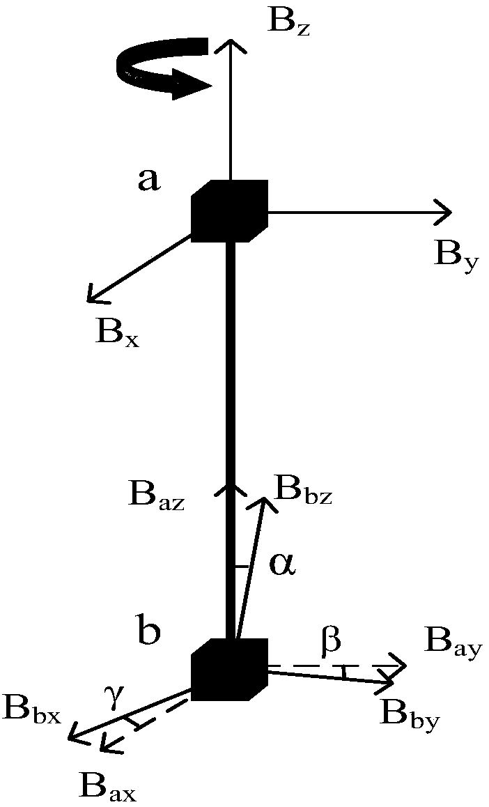
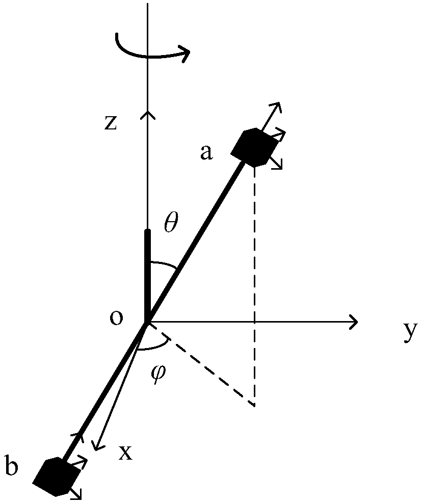
[0043] In the embodiment, such as figure 1 As shown, the vector magnetic gradiometer is composed of vector magnetometers placed in parallel; where the two modules a and b refer to the first vector magnetometer a and the second vector magnetometer b; B ax , B ay , B az Is the output data of the x, y, and z axes of the magnetometer a; B bx , B by , B bz Is the output data of the x, y, and z axes of th...


PUM


Abstract

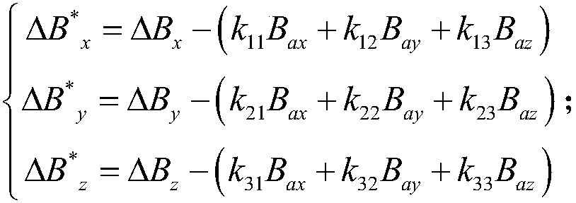
The invention discloses a motion type magnetic target locating method based on a vector magnetic gradiometer. The motion type magnetic target locating method comprises the following steps that (1) the structural error of two sets of vector magnetometers forming the vector magnetic gradiometer is compensated so that the signal output of the two sets of vector magnetometers is maintained to be consistent; (3) the vector magnetic gradiometer is enabled to rotate around a vertical axis in a magnetic abnormal space, the magnetic field direction gradient data of the magnetic gradiometer at the rotating azimuth angle are acquired, and magnetic field full tensors are acquired according to the relation between the direction gradient and the azimuth angle; and (3) magnetic target locating is performed by using the magnetic field full tensors. According to the motion type magnetic target locating method, the structural error compensation problem of the vector magnetic gradiometer is solved by using the mode of triaxial coefficient compensation so that the output of the two sets of vector magnetometers forming the magnetic gradiometer is enabled to be correspondingly consistent; and the structural error is eliminated so that high-resolution detection can be realized.

Description

Technical field [0001] The invention belongs to the field of magnetic detection technology, and more specifically, relates to a moving magnetic target positioning method based on a vector magnetic gradiometer. Background technique [0002] Magnetic detection method is often used in geological prospecting, biomedicine, navigation and positioning, unexploded object detection and other fields; in these fields, the application of high-resolution total magnetic field intensity detection method can facilitate the detection of the movement of magnetic objects, but realize the accuracy of magnetic objects Positioning is more difficult. The detection method based on the magnetic gradiometer can effectively realize the target positioning, but the installation and production of the vector magnetic gradiometer needs to ensure that the axes of the two sets of vector magnetometers constituting the vector magnetic gradiometer are strictly parallel and the electrical performance is strictly symm...

Claims


Application Information

Patent Timeline
Patent Type & Authority Patents(China)
IPC IPC(8): G01V3/08
CPCG01V3/081
Inventor 林春生贾文抖孙玉绘
Owner NAVAL UNIV OF ENG PLA
Learn More