
Support structure applied to miniaturized reflector

A technology for supporting structures and mirrors, applied in installation, optics, instruments, etc., can solve the problems of deformation of optical components, affecting the imaging quality of the system, and the optical surface shape of optical components cannot reach the theoretical design value, etc., to solve the problem of mirror surface The effect of deformation and avoidance of additional stress

Active Publication Date: 2017-02-15
INST OF OPTICS & ELECTRONICS - CHINESE ACAD OF SCI
View PDF5 Cites 2 Cited by
  • Summary
  • Abstract
  • Description
  • Claims
  • Application Information

AI Technical Summary

Problems solved by technology

However, due to the existence of other uncertain factors such as machining errors, additional stress usually occurs when the support structure and optical components are integrated and assembled, causing additional deformation of the optical components, so that the optical surface shape of the optical components cannot reach the theoretical design value , thus affecting the imaging quality of the system

Method used


Image

  • Support structure applied to miniaturized reflector
  • Support structure applied to miniaturized reflector

Examples


Embodiment Construction

[0015] The present invention will be described in detail below in conjunction with the accompanying drawings and specific embodiments.

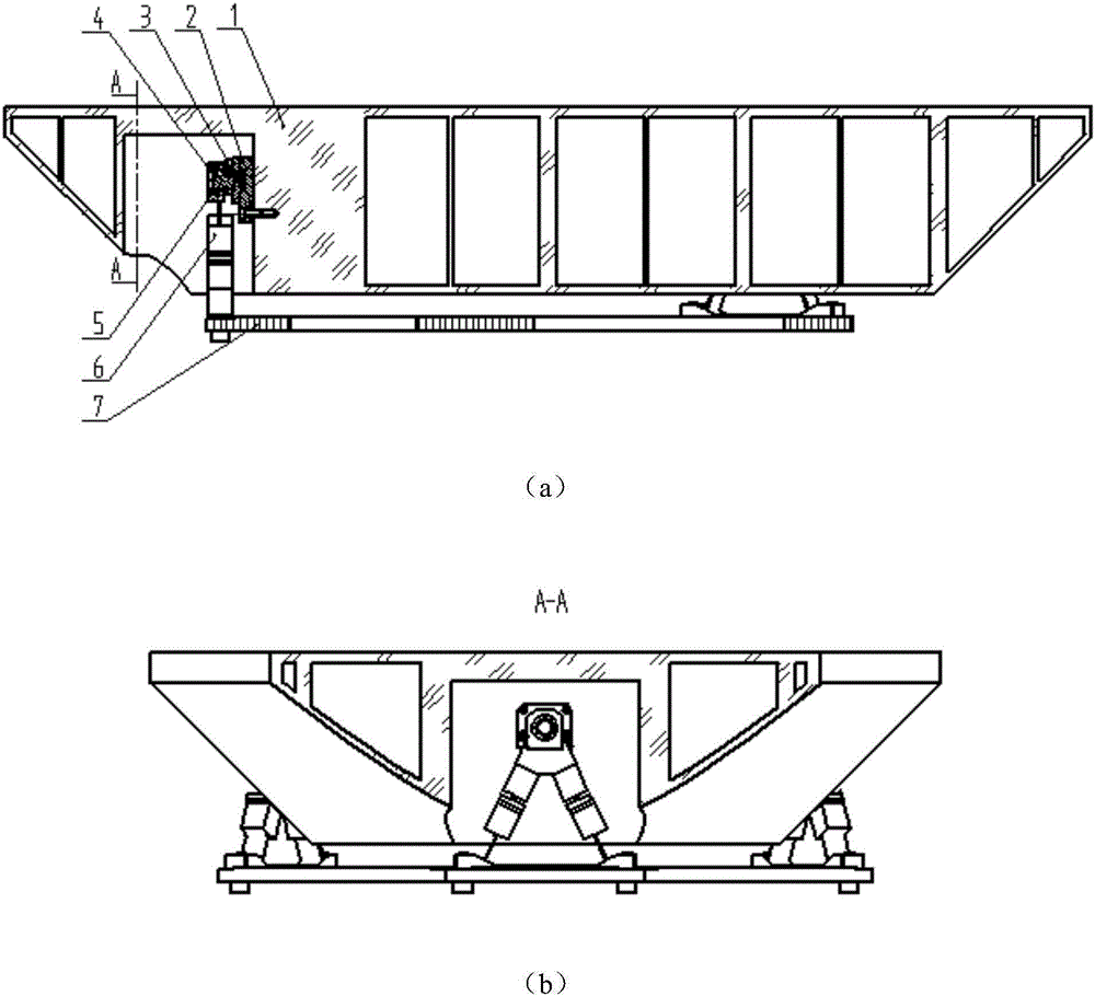
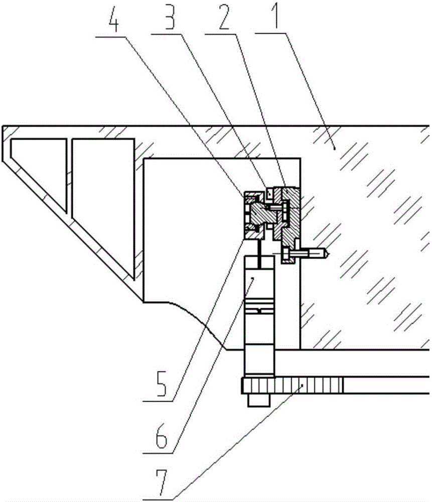
[0016] The present invention is implemented through the following technical solutions. figure 1 It is a structural diagram of the present invention, which includes a reflector 1 with grooves on the back, a bonding block 2, a connecting screw 3, a ball head 4, a conical pressure ring 5, a supporting foot 6 and a connecting plate 7. Adhesion is adopted between the reflector 1 and the three adhesive blocks 2, figure 2 It is an enlarged view of the reflector 1, one of the adhesive blocks and the supporting structure. The reflector 1 and the bonding block 2 are respectively connected to the three support feet 6 through the ball head 4, and the conical pressure ring 5 presses the ball head 4 so that the support foot 6 can rotate flexibly relative to the reflector 1 without gaps. Thereby eliminating the additional stress that occurs when the scre...


PUM


Abstract

The invention relates to a support structure applied to a miniaturized reflector. The support structure comprises a back-grooved reflector (1), a bonding block (2), a connection screw (3), a bulb (4), a taper clamping ring (5), a support leg (6) and a connection plate (7). A conventional similar support structure hides mechanical members in the caliber of an optical device so as to eliminate influences exerted by the support structure on the detection capability and precision of infrared radiation, however, during structural assembling, due to existence of work errors and bonding position errors, when the support leg (6) is in butt joint with the connection plate (7), an overdetermined phenomenon occurs, when the flexibility of the support leg is not sufficient enough to overcome additional stress brought by overdetermining, the optical surface of an optical element generates additional deformation, and thus the system imaging quality is affected. By use of bulb connection, the support leg (6) is enabled to have a degree of freedom in three rotation directions, and thus the influence exerted by the additional stress on the optical surface is solved. The support structure applied to the miniaturized reflector has the advantages of simple structure, stable work performance, mature processing technology and the like.

Description

technical field [0001] The invention relates to the technical field of optical element support structures, in particular to a support structure applied to small mirrors. Background technique [0002] Optical components are located in the optical path, and their supporting structures are usually larger than their apertures, so they will block the optical path of the system to a certain extent. Especially for infrared telescopes, the noise generated by the thermal radiation of the system itself is one of the main sources of noise when the system detects weak infrared radiation. The supporting structure of each optical component located in the optical path of the system exceeds the aperture of the optical device, and part of the heat radiation will reach the infrared detector through the light propagation route, reducing the system's ability to detect faint infrared targets. In recent years, support structures hidden on the back of optical components have been maturely used. ...

Claims


Application Information

Patent Timeline
Patent Type & Authority Applications(China)
IPC IPC(8): G02B7/02
CPCG02B7/02
Inventor 李程唐金龙
Owner INST OF OPTICS & ELECTRONICS - CHINESE ACAD OF SCI
Learn More