Large axial chromatic aberration linear dispersion object lens

An axial chromatic aberration and linear technology, applied in the field of optical objective lenses, can solve the problems of unincorporated imaging quality, large objective lens size, and enlarged objective lens size, etc. Effect

Active Publication Date: 2017-02-15
NANJING INST OF ADVANCED LASER TECH
View PDF10 Cites 6 Cited by
  • Summary
  • Abstract
  • Description
  • Claims
  • Application Information

AI Technical Summary

Problems solved by technology

The people such as A.Miks provided the solution method of two-piece structure linear dispersion objective lens in Theory of hyperchromats with linear longtitudinal chromatic aberration (Proc.Of SPIE Vol.5945 59450Y), and provided the example of linear dispersion objective lens, but The ratio of the axial dispersion range of the objective lens to the system focal length is less than 0.03, and the imaging quality is not taken into consideration in the design; Chinese patent document CN104238077A also discloses a linear dispersion objective lens, but the ratio of the axial dispersion range of the objective lens to the system focal length It is only about 0.04, and the objective lens has the problems of large size and complex structure, and it is difficult to implement; US Patent Document US8248598B2 discloses an objective lens design that can increase the ratio of axial dispersion range to system focal length by using a multi-group splicing method, but There is no explanation on the linearity of the objective lens, and the size of the objective lens needs to increase with the increase of the axial dispersion range

Method used


Image

  • Large axial chromatic aberration linear dispersion object lens
  • Large axial chromatic aberration linear dispersion object lens
  • Large axial chromatic aberration linear dispersion object lens

Examples


Embodiment Construction

[0032] In order to make the technical problems, technical solutions and advantages to be solved by the present invention clearer, the following will describe in detail with reference to the drawings and specific embodiments.

[0033] Aiming at the existing problems, the present invention provides a linear dispersion objective lens with large axial chromatic aberration. The linear dispersion objective lens can be used for non-contact measurement based on spectral confocal technology. It plays a role in real-time or non-real-time detection of manufacturing.

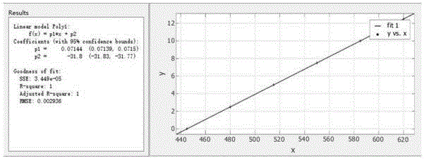
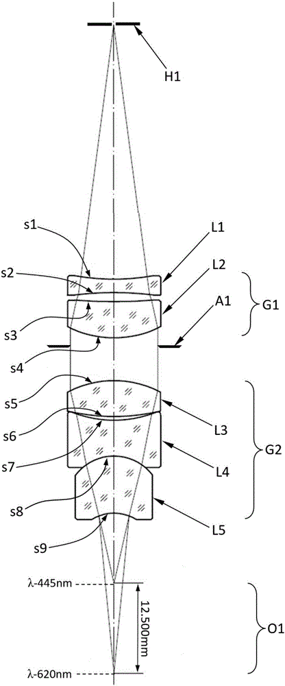
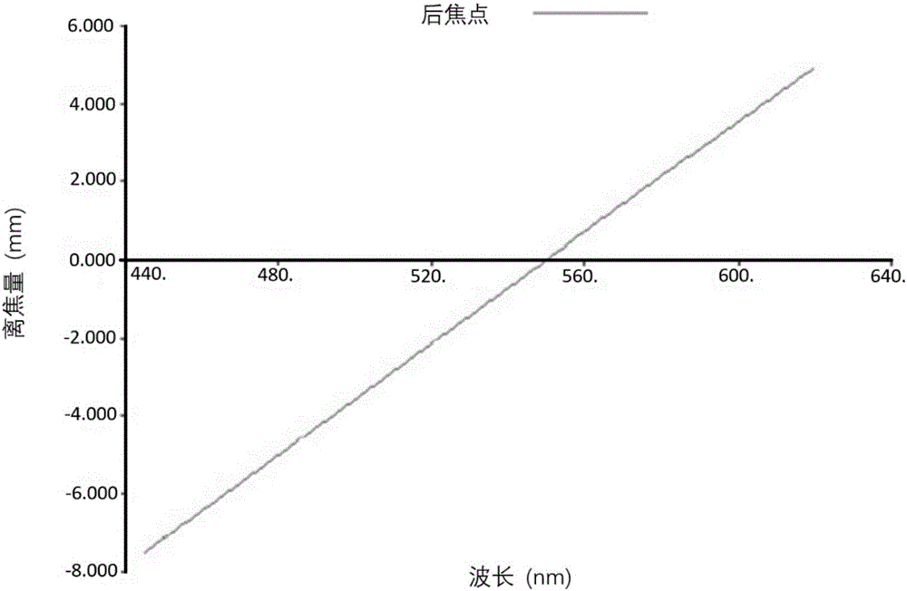
[0034] Such as figure 1 It is an embodiment of the linear dispersion objective lens with large axial chromatic aberration of the present invention.

[0035] The linear dispersion objective lens of the present invention specifically includes a collimating lens group and a focusing lens group, the collimating lens group and the focusing lens group are sequentially arranged along the optical axis between the pinhole of the li...


PUM


Abstract

The embodiment of the invention provides a large axial chromatic aberration linear dispersion object lens. The object lens comprises a collimating lens group with positive focusing luminosity and a focusing lens group with positive focusing luminosity, the collimating lens group and the focusing lens group are arranged along the optical axis in order between a light source pinhole and measured object, the collimating lens group is close to the light source pinhole, and the focusing lens group is close to the measured object. The object lens system comprehensively considers the balance of the linearity of the dispersion object lens and the system aberration correction, and the collimating lens group and the focusing lens group are both positive lens groups and have the effect of collimation first and then focusing. The collimating lens group includes an aspheric lens to allow the ratio of the axial direction dispersion range of the linear dispersion object lens and the system focal length to be larger than 0.2 so as to entirely reduce the size of the object lens, reduce the processing difficulty and allow the object lens to have excellent linearity; and moreover, an additional arrival aperture diaphragm can limit the incident ray angle, prevent the adjustment process from being difficult because the structure of the dispersion object lens is complicated, and improve the processing precision.

Description

technical field [0001] The invention belongs to the technical field of optical objective lenses, in particular to a linear dispersion objective lens with large axial chromatic aberration, which can be used for non-contact measurement based on spectral confocal technology. Background technique [0002] The spectral confocal displacement sensor is a non-contact sensor based on the confocal principle and uses a wide-spectrum light source. Its highest precision can reach the nanometer level, and it can measure almost all material surfaces. It is widely used due to its non-contact and high-precision characteristics. The basic principle is that the wide-spectrum light source produces spectral dispersion after passing through the linear dispersion objective lens, and forms a series of focal points along the optical axis of the dispersion objective lens after passing through the confocal aperture. , only the reflected beam of the corresponding wavelength that satisfies the object-im...

Claims


Application Information

Patent Timeline
Patent Type & Authority Applications(China)
IPC IPC(8): G02B15/16G01B11/02
CPCG01B11/02G02B15/142
Inventor 庆祖林曾爱军黄惠杰
Owner NANJING INST OF ADVANCED LASER TECH
Why Eureka
Try Eureka