
Large-pitch thread turning tool design method

A cutting tool design and large pitch technology, applied in turning equipment, cutting tools for lathes, calculations, etc., can solve problems such as inability to solve the problem of consistency in the distribution of left and right thread surfaces, cutting quality problems that cannot be solved, and cutting efficiency that cannot be guaranteed. , to achieve the effect of improving the processing accuracy and the consistency of the processing surface quality, avoiding deformation and excessive wear, and improving the processing quality

Active Publication Date: 2017-02-15
HARBIN UNIV OF SCI & TECH
View PDF5 Cites 5 Cited by
  • Summary
  • Abstract
  • Description
  • Claims
  • Application Information

AI Technical Summary

Problems solved by technology

[0004] The existing large-pitch thread tool design method is mainly based on the matching of thread structure features. According to the feature parameters of the part, the matching tool is selected to complete the design of the cutting edge structure parameters; experiments are carried out based on the designed tool to select the matching tool. In this method, the surface morphology and precision of thread machining can only be adjusted by changing the process parameters, and the cutting quality problems caused by the tool structure cannot be solved, and the cutting efficiency cannot be guaranteed
The design goal of the existing method is as long as the surface roughness does not exceed the maximum value, and the width of the wear area is smaller than the maximum value. This method cannot solve the problem of the distribution consistency of the left and right thread surfaces under specific constraints.

Method used


Image

  • Large-pitch thread turning tool design method
  • Large-pitch thread turning tool design method
  • Large-pitch thread turning tool design method

Examples


Embodiment Construction

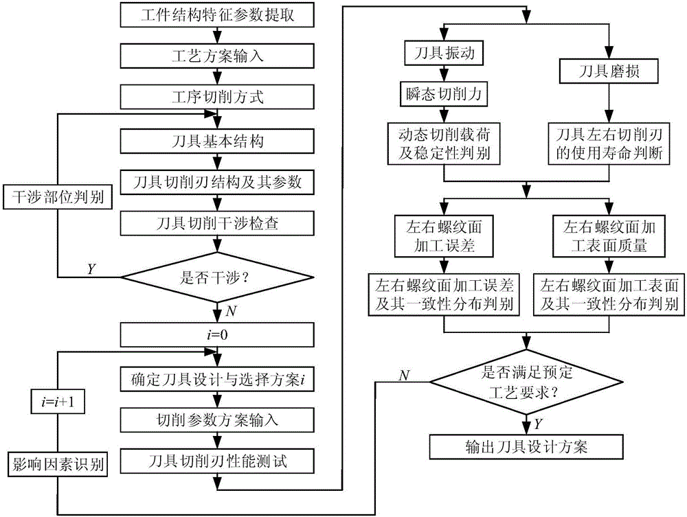
[0032] refer to figure 1 , the large-pitch thread turning tool design method of the present invention comprises the following steps:

[0033] 1. Determine the process plan and process cutting method according to the structural characteristics of the processed large-pitch thread workpiece, and set the cutting tool suitable for the basic structure of the tool for turning the large-pitch thread workpiece according to the process plan and process cutting method. The basic structure includes the tool cutting edge structure and its parameters;

[0034] 2. Check the tool cutting interference. If there is interference, judge the interference position of the cutting tool; if there is no interference, determine to use the cutting tool to perform cutting experiments on the workpiece;

[0035]3. Input the cutting plan to turn the workpiece, and obtain the tool vibration signal and the wear image of the tool flank during the cutting process;

[0036] 4. Judging the cutting plan of the cu...


PUM


Abstract

The invention provides a large-pitch thread turning tool design method. According to the technical main points, the method comprises the steps of (1) determining a process scheme and a procedure cutting method according to structure characteristics of a processed large-pitch thread workpiece and setting a cutting tool with a basic tool structure suitable for turning the large-pitch thread workpiece, wherein the basic tool structure of the cutting tool comprises a tool cutting edge structure and parameters thereof; (2) carrying out tool cutting interference checking, if interference does not exist, determining a cutting experiment on the workpiece by using the cutting tool; (3) inputting a cutting scheme to turn the workpiece and obtaining a tool vibration signal and a rear tool surface abrasion image of the tool; and (4) evaluating the cutting scheme of the cutting tool by taking the dynamic load consistency of left and right edges of the cutting tool, the left, right and back tool surface abrasion consistency of the cutting tool, the processing precision of left and right thread surfaces of the workpiece and the processing surface quality consistency as design objectives. According to the large-pitch thread turning tool design method, the loads of the left and right edges of the tool are improved; the abrasion is reduced; the consistency is good; and the processing quality of the workpiece is improved.

Description

Technical field: [0001] The invention relates to the field of cutting tool design, and in particular relates to a design method for a large-pitch thread turning tool. Background technique: [0002] A thread with a pitch greater than 4mm is defined as a large pitch thread. This type of part is used as a large-scale press adjustment component screw to control the position accuracy between the upper and lower templates, which has an important impact on the static and dynamic accuracy of the press machine. Large-pitch external threads have wide and deep tooth grooves, large pitch and axial length, and are non-standard threads with large machining allowances. The pitch, tooth profile accuracy, and thread surface quality consistency of the left and right thread surfaces are high. [0003] The existing thread cutting tools mainly include turning tools, dies, thread rolling wheels, thread rolling boards and taps; ordinary small and medium-sized thread cutting tools are difficult to ...

Claims


Application Information

Patent Timeline
IPC IPC(8): G06F17/50B23B27/00
CPCB23B27/00G06F30/17
Inventor 赵娇姜彬郑敏利
Owner HARBIN UNIV OF SCI & TECH
Learn More