

Reflection type quantum dot television
A quantum dot and reflective technology, which is applied in the field of reflective quantum dot TV, can solve problems such as narrow color gamut, high energy consumption of LED lamps, and problems of electronic excitation light efficiency, and achieve high color gamut and high brightness.
- Summary
- Abstract
- Description
- Claims
- Application Information
AI Technical Summary
Problems solved by technology
Method used
Image

Examples
Embodiment Construction
[0028] according to Figure 1~4 implement.
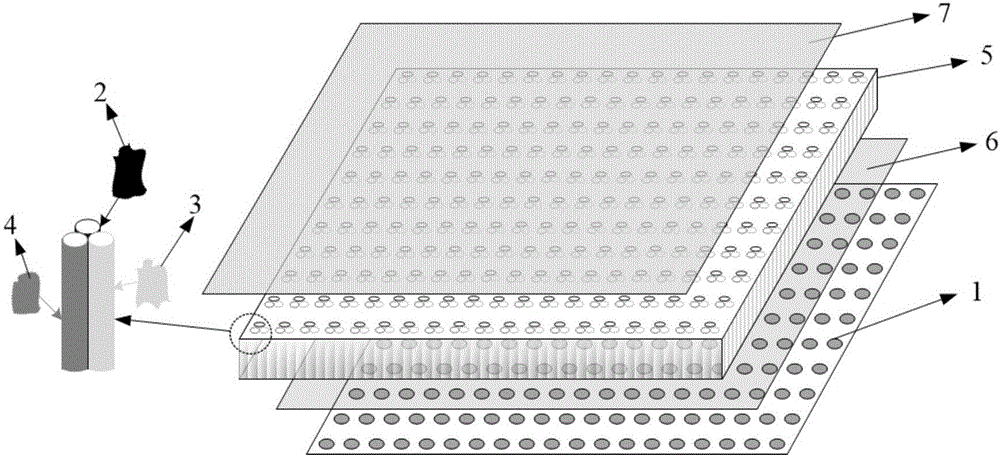
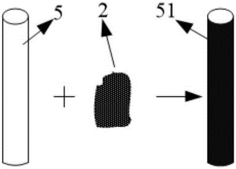
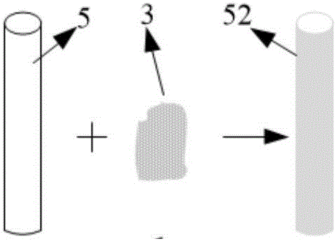
[0029] The present invention consists of a digital blue surface light source 1, blue quantum dots 2, blue photoluminescence red quantum dots 3, blue light photoluminescence green quantum dots 4, an optical fiber layer 5, an anti-reflection layer 6 on the incident surface of the optical fiber layer, and a surface imaging layer 7 composition such as figure 1 shown.
[0030] The digital blue surface light source 1 of the present invention can be an LED digital blue surface light source composed of small-pitch LED blue light lamps, which can control the gray level of each LED point light source, or can be composed of a blue surface light source + TFT transparent Liquid crystal or white surface light source + blue filter + TFT transparent liquid crystal to form each point light source with controllable gray level LCD digital blue surface light source, also can use OLED principle to manufacture each point light source with controllable ...
PUM
 Abstract
Description
Claims
Application Information