AI technical title is built by PatSnap AI team. It summarizes the technical point description of the patent document.
A technology for driving circuits and sensing voltages, applied in instruments, static indicators, etc., can solve the problems of poor products, high production costs, and difficult driving circuit processes, and achieve the effect of reducing production costs.
Active Publication Date: 2017-02-15
BOE TECH GRP CO LTD
View PDF7 Cites 19 Cited by
Summary
Abstract
Description
Claims
Application Information
AI Technical Summary
This helps you quickly interpret patents by identifying the three key elements:
Problems solved by technology
Method used
Benefits of technology
Problems solved by technology
[0005] The process of generating the driving circuit is quite difficult, which sometimes causes abnormalities in the generated driving circuit. On the basis of the abnormal driving circuit, other parts of the array substrate are continued to be generated, which is prone to defective products and makes the production cost higher.
Method used
Image
Click on the blue label to locate the original text in one second.
Reading with bidirectional positioning of images and text.
Examples
Embodiment 1
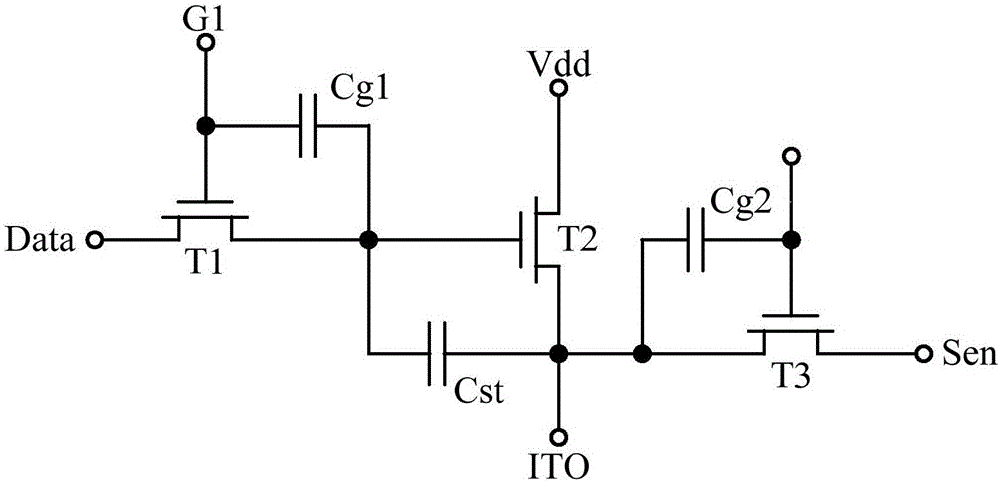
[0038] An embodiment of the present invention provides a driving circuit, the driving circuit is located on an array substrate, and the array substrate further includes a pixel unit corresponding to the driving circuit, and the driving circuit is used to drive the corresponding pixel unit to emit light. see Picture 1-1 , the drive circuit includes:
[0040] The gate of the first transistor T1 is connected to the gate scanning input terminal G1, the first pole is connected to the data input terminal Data, the second pole is connected to the gate of the second transistor T2, the first metal layer of the pixel storage capacitor Cst and the first The first end of the parasitic capacitor Cg1 is connected;
[0041] The first pole of the second transistor T2 is connected to the power supply te...
Embodiment 2
[0050] An embodiment of the present invention provides a method for detecting a driving circuit, and the method is used for detecting the driving circuit provided in Embodiment 1.
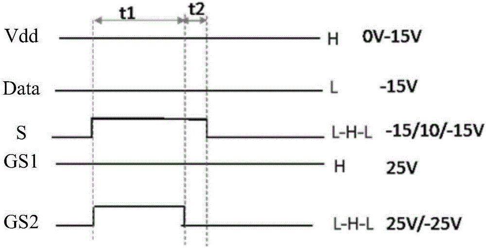
[0051] see diagram 2-1 As shown in the timing signal diagram, the present invention provides data signal Data, gate line scanning signal GS1, voltage signal V, first control signal Sen and second control signal GS2; , the gate scan signal GS1 , the voltage signal V, the first control signal S and the second control signal GS2 detect the driving circuit.
[0052] see Figure 2-2 , the method flow for detecting the drive circuit includes:
[0053] Step 201: Input the data signal Data, the gate line scanning signal GS1, the voltage signal V and the first level of the first level to the data input terminal Data, the gate scanning input terminal G1, the power supply terminal Vdd and the sensing voltage terminal Sen respectively of the driving circuit. a control signal S.
[0054] see diagram 2-1 , ...
PUM
Abstract
The invention discloses a method of testing a driving circuit, and belongs to the field of display. The method comprises the following steps: inputting a data signal, a gate line scanningsignal, a voltagesignal, and a first control signal of a first level to a data input end, a gate scanning input end, a power end and a sensing voltage end of a driving circuit respectively; making a pixel storage capacitor perform charging by inputting a second control signal of a second level to a sensing scanning input end of the driving circuit, and measuring a first voltage at the anode end of an organic light emitting diodeOLED of the driving circuit; making the pixel storage capacitor perform discharging by inputting a third control signal of a third level to the sensing scanning input end of the driving circuit, and measuring a second voltage at the anode end of the OLED of the driving circuit; and determining whether the driving circuit is abnormal according to the first voltage and the second voltage. The cost of production can be reduced.
Description
technical field [0001] The invention relates to the display field, in particular to a method for detecting a driving circuit. Background technique [0002] An AMOLED (Active-matrix organic light emitting diode, active matrix organic light emitting diode) screen includes components such as an array substrate. The array substrate includes a plurality of pixel units, and each pixel unit corresponds to a driving circuit. The driving circuit is used to drive its corresponding pixel unit to emit light. [0003] When producing the array substrate, the driving circuit can be generated on the glass substrate through a patterning process, and the pixel unit corresponding to the driving circuit and other parts of the array substrate can be generated on the glass substrate through the patterning process, and the other parts can be It is the filter layer, black matrix and other components. [0004] In the process of realizing the present invention, the inventor finds that there are at...
Claims
Application Information
Patent Timeline
Application Date:The date an application was filed.
Publication Date:The date a patent or application was officially published.
First Publication Date:The earliest publication date of a patent with the same application number.
Issue Date:Publication date of the patent grant document.
PCT Entry Date:The Entry date of PCT National Phase.
Estimated Expiry Date:The statutory expiry date of a patent right according to the Patent Law, and it is the longest term of protection that the patent right can achieve without the termination of the patent right due to other reasons(Term extension factor has been taken into account ).
Invalid Date:Actual expiry date is based on effective date or publication date of legal transaction data of invalid patent.

