Switch element, the preparation method of the switch element, array substrate and display apparatus

A technology for switching elements and array substrates is applied in the fields of switching elements and their preparation, array substrates and display devices, and can solve the problems of area crowding of display and reduction of aperture ratio of pixel area, etc.

Pending Publication Date: 2017-02-15
HEFEI BOE OPTOELECTRONICS TECH +1
View PDF8 Cites 13 Cited by
  • Summary
  • Abstract
  • Description
  • Claims
  • Application Information

AI Technical Summary

Problems solved by technology

However, in the case of increasing W/L in these ways, the area for display in each pi

Method used


Image

  • Switch element, the preparation method of the switch element, array substrate and display apparatus
  • Switch element, the preparation method of the switch element, array substrate and display apparatus
  • Switch element, the preparation method of the switch element, array substrate and display apparatus

Examples


Embodiment Construction

[0032] In order to make the purpose, technical solutions and advantages of the embodiments of the present invention more clear, the following will clearly and completely describe the technical solutions of the embodiments of the present invention in conjunction with the drawings of the embodiments of the present invention. Apparently, the described embodiments are some, not all, embodiments of the present invention. Based on the described embodiments of the present invention, all other embodiments obtained by persons of ordinary skill in the art without creative efforts shall fall within the protection scope of the present invention.

[0033] Unless otherwise defined, the technical terms or scientific terms used in the present disclosure shall have the usual meanings understood by those skilled in the art to which the present invention belongs. "First", "second" and similar words used in the present disclosure do not indicate any order, quantity or importance, but are only use...


PUM


Abstract

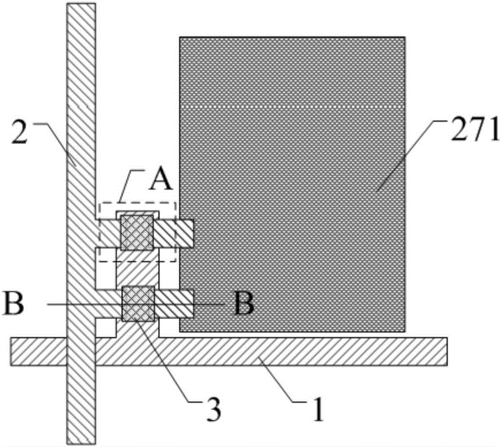
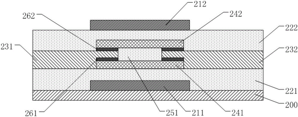
The invention discloses a switch element, the preparation method of the switch element, array substrate and display apparatus. The switch element comprises a substrate; a first film transistor arranged on the substrate; and a second film transistor arranged on the first film transistor. The first film transistor consists of a first electrode and a second electrode. The first film transistor and the second film transistor share the first electrode and the second electrode. According to the switch element of the invention, two film transistors are in parallel arrangement with one above the other. This design increases the open-state current of the switch element while reducing the size of the switch element. In addition, as the two film transistors share the same source electrode layer and the drain electrode layer, the preparation technology for the switch element is simplified and the cost is reduced.

Description

technical field [0001] Embodiments of the present invention relate to a switch element, a manufacturing method thereof, an array substrate, and a display device. Background technique [0002] With the development of liquid crystal display technology, current consumers have higher and higher requirements for product resolution, and products with high resolution have gradually become the mainstream of the market, and high resolution means that the charging time for each row of pixels in the device is longer shortening, the corresponding switching element (such as a thin film transistor) needs to increase the on-state current to complete charging and discharging the pixel electrode in a shorter time. In terms of the structural design of the array substrate, the most direct way to increase the on-state current of the switching element is to increase the W / L (width-to-length ratio) of the switching element. For example, a larger W / L can be achieved by increasing the size of a si...

Claims


Application Information

Patent Timeline
IPC IPC(8): H01L27/12H01L21/77
CPCH01L27/1214H01L27/1259G02F1/13624H01L27/1251H01L29/41733H01L29/45H01L27/124H01L29/495G02F1/1368H01L29/517H01L27/127H10K59/1213
Inventor 廖力勍李红敏王迎王栋
Owner HEFEI BOE OPTOELECTRONICS TECH
Why Eureka
Try Eureka