Method and device for automatically testing optical loss of dual-parallel MZI-type electro-optical modulator

An electro-optic modulator and optical loss technology, which is applied in the field of communication, can solve the problems of large test workload and achieve the effects of simple test circuit design, simple test method, and improved production efficiency

Active Publication Date: 2017-02-15
GUANGXUN SCI & TECH WUHAN
View PDF3 Cites 11 Cited by
  • Summary
  • Abstract
  • Description
  • Claims
  • Application Information

AI Technical Summary

Problems solved by technology

However, due to device design, the optical loss of the dual-parallel MZI electro-optic modulator often has a certain wavelength dependence. Therefore, in the actual optical production process, it is necessary to test the optical insertion loss of the device under all ITU wavelength channels
For a WDM optical communication system with a frequency interval of 50Ghz, it is necessary to test the optical loss of the modulator at 96 wavelengths, which is a large test workload

Method used


Image

  • Method and device for automatically testing optical loss of dual-parallel MZI-type electro-optical modulator
  • Method and device for automatically testing optical loss of dual-parallel MZI-type electro-optical modulator
  • Method and device for automatically testing optical loss of dual-parallel MZI-type electro-optical modulator

Examples


Embodiment Construction

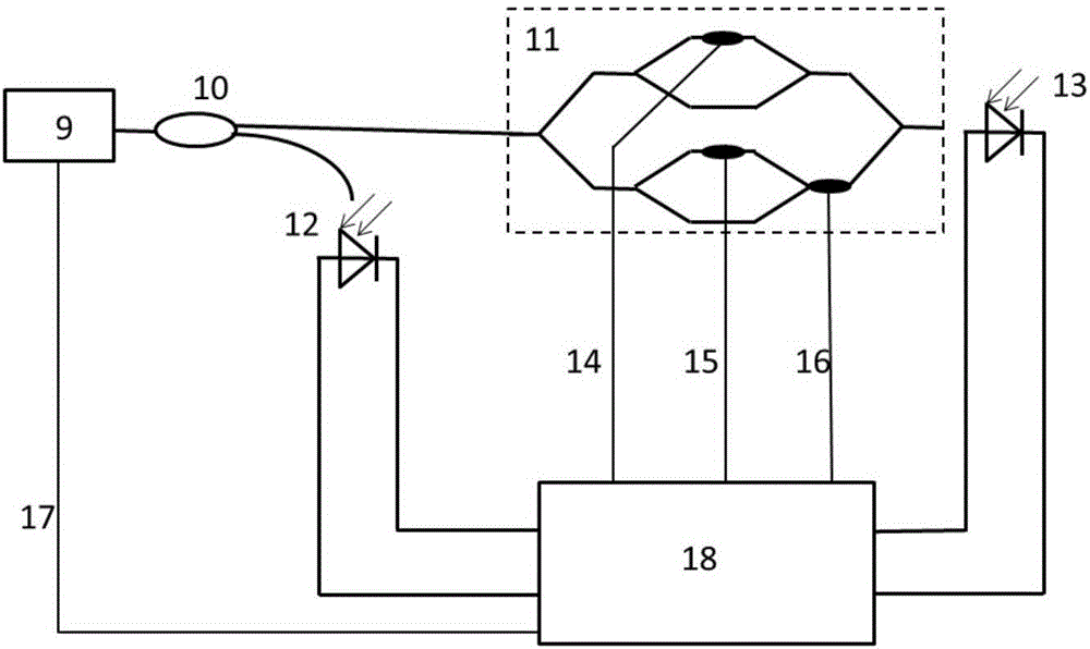
[0033] The automatic test method and device for the optical loss of the double-parallel MZI electro-optic modulator in the invention will be described in detail below in combination with the embodiments and the accompanying drawings.

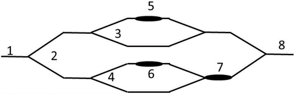
[0034] figure 1 It is a schematic diagram of the structure of the parallel MZI electro-optic modulator. The parallel MZI is composed of two sub-MZIs (I-way sub-MZI 3, Q-way sub-MZI 4) in parallel to form a mother MZI 2. On the road, I-channel MZI phase-modulating electrodes 5, Q-channel MZI phase-modulating electrodes 6, and Q-channel MZI phase-modulating electrodes 7 are made respectively. Appropriate bias voltage is applied to the sub-MZI phase-modulating electrode 6 of the Q path and the parent MZI phase-modulating electrode 7 to adjust the output optical power of the optical output terminal 8 of the modulator. When testing the optical insertion loss of the electro-optic modulator, it is not necessary to load the radio frequency electrical s...


PUM


Abstract

The invention discloses a method for automatically testing optical loss of a dual-parallel MZI-type electro-optical modulator. The method comprises the steps of: setting a light emergent wavelength path of a testing light source, and acquiring light incident power of the modulator and light emergent power P0 of the modulator when a bias voltage is not applied; regulating a bias voltage of an I path of the modulator to enable light emergent power of the modulator to reach the maximum; regulating a bias voltage of a Q path of the modulator to enable light emergent power of the modulator to reach the maximum; regulating a bias voltage of a P path of the modulator to enable light emergent power of the modulator to reach the maximum; recording current light emergent power P of the modulator, subtracting the light emergent power P0 from a value of the light emergent power P to obtain a power increment delta P, and calculating to obtain an increment percentage delta P / P; comparing the increment percentage delta P / P with a preset threshold percentage, and when the increment percentage delta P / P is greater than the preset threshold percentage, returning to the last step; and if the increment percentage delta P / P is smaller than or equal to the preset threshold percentage, proceeding to calculate the optical loss of the wavelength path. According to the invention, the testing method is simple and rapid, and testing circuit design is simple.

Description

technical field [0001] The invention relates to an automatic test method and device for the optical loss of an electro-optic modulator, in particular to an automatic test method and device for the optical loss of a double-parallel MZI type electro-optic modulator. The invention belongs to the field of communication. Background technique [0002] In the digital transmission system, the use of DPSK and DQPSK has been very common, which indicates that the use of phase-sensitive coding and transmission technology will become a trend. At the same time, in just two decades, the optical device industry has made great progress, among which the output power, line width, stability and noise of lasers, as well as the bandwidth, power capacity and common-mode rejection ratio of photodetectors have all been improved. The performance of microwave electronic devices has also been greatly improved, and these advances have made it possible to commercialize coherent optical communication syst...

Claims


Application Information

Patent Timeline
Patent Type & Authority Applications(China)
IPC IPC(8): H04B10/079H04B10/69G02F1/03
CPCG02F1/0327H04B10/07955H04B10/07957H04B10/691
Inventor 黄钊张博钱坤胡毅马卫东
Owner GUANGXUN SCI & TECH WUHAN
Why Eureka
Try Eureka