Urine flow control system and magnetic actuator device

A technology of actuator device and control system, which is applied in the direction of drainage device, wound drainage device, anti-incontinence device, etc., and can solve the problem of users getting themselves dirty

Active Publication Date: 2018-07-10
MAGCATH APS
View PDF5 Cites 0 Cited by
  • Summary
  • Abstract
  • Description
  • Claims
  • Application Information

AI Technical Summary

Problems solved by technology

The fact that the prior art actuator magnets are hand-held involves the risk that the user will get himself dirty, since the actuator magnet is held close to the valve body, and this can be seen as prior art with magnetically Problems with conduit fittings for actuated discharge control valves

Method used


Image

  • Urine flow control system and magnetic actuator device
  • Urine flow control system and magnetic actuator device
  • Urine flow control system and magnetic actuator device

Examples


Embodiment Construction

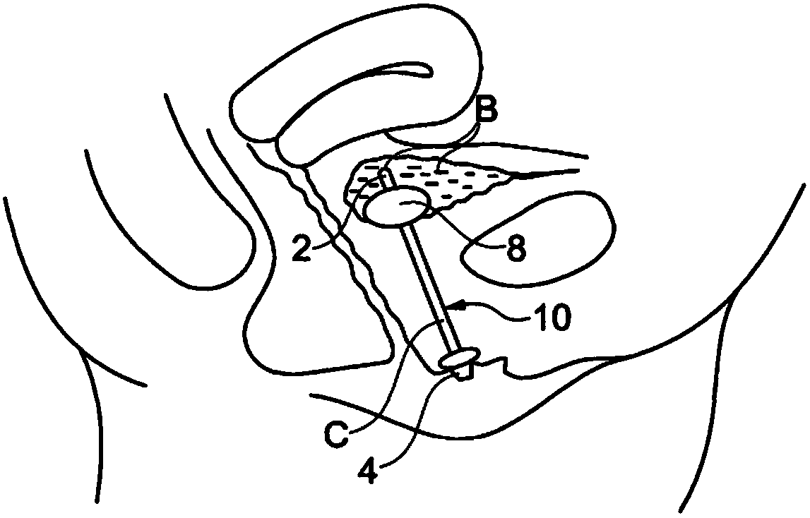
[0020] It is important to emphasize that incontinent persons as well as persons suffering from problems emptying their bladders can equally use the urinary flow control systems discussed below. However, for convenience, the urinary flow control system of the present invention will be described below in the context of an incontinence device.

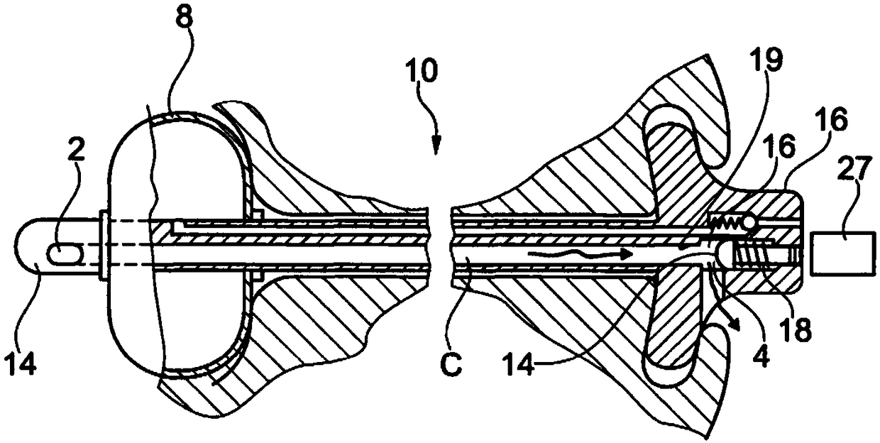
[0021] figure 1 One embodiment of a prior art female incontinence control device is shown in the form of a catheter device 10 with a urinary tube C having an inlet 2 at the proximal portion of the catheter device 10 closest to the bladder B. and outlet 4 at its distal portion. In order to maintain the correct position of the catheter device 10 within the urethra, the bladder junction 8 at the proximal part of the catheter device 10 is used. As shown, bladder junction 8 may be an inflatable balloon.

[0022] like figure 1 The prior art catheter device 10 shown illustrates the general type of incontinence device or urinary flow control ...


PUM


Abstract

The present invention relates to a urinary flow control system (50) comprising a catheter device (10,100) for insertion into the urethra, the catheter device (10,100) having a proximal portion (14) and an opposing distal portion (16, 102), tube (C) between said proximal portion (14) and said distal portion (16), tube (C) having a urine inlet (C) located in said proximal portion (14) 2) and a urine outlet (4, P) located at the distal portion (16, 102), and a magnetically actuable valve at the distal portion (16, 102) to control the flow of urine from the A catheter device (10, 100) discharges through said outlet (4, P), and a magnetic actuator device having an actuator magnet (201), a magnetic actuator separate from said catheter device (10, 100) Device for operating said valve, characterized in that said magnetic actuator device (200) includes a housing (205) for receiving urine discharged from said catheter device (10, 100), said housing (205) having a first open end (202) and a second end, the first open end being configured to receive said distal portion (16) having said magnetically actuable valve and said outlet (4, P) , 102), the housing (205) having the actuator magnet (201) at the first end (202).

Description

technical field [0001] The present invention relates to an improved urinary flow control system involving the use of a solenoid valve body and a magnetic actuator arrangement, and to a magnetic actuator arrangement for use in said system. Background technique [0002] Incontinence refers to the inability of any bodily organ to inhibit the expulsion of its contents; within the scope of the present invention, incontinence is considered to be the involuntary discharge or emptying of urine. This could be, for example, during movement, such as when jumping, or when sneezing or laughing, when a person suffering from incontinence can have problems. [0003] People suffering from incontinence are often forced to wear pads that collect urine from the urethra. In addition, people suffering from incontinence suffer from an unpleasant odor caused by urination, which can be uncomfortable and embarrassing. Therefore, there is a need for a device that prevents uncontrolled urination. ...

Claims


Application Information

Patent Timeline
Patent Type & Authority Patents(China)
IPC IPC(8): A61F2/00A61F5/451
CPCA61F2/0018A61F5/451A61M2025/0076A61M25/0017A61M27/00A61M25/0075A61M2025/0078
Inventor N·埃里克斯特卢普
Owner MAGCATH APS
Why Eureka
Try Eureka