High-efficiency denitrification equipment

A high-efficiency, denitrification technology, applied in the field of denitrification, can solve the problems of uneven gas temperature distribution, uneven flue gas temperature distribution, and uneven flue gas temperature distribution in the denitrification reaction area, and achieve the effect of diffuse injection area and good thermal conductivity

Pending Publication Date: 2017-02-22
SHANGHAI WISEBOND TECH +1
View PDF9 Cites 1 Cited by
  • Summary
  • Abstract
  • Description
  • Claims
  • Application Information

AI Technical Summary

Problems solved by technology

The main reason is that the denitrification efficiency is affected by the following factors: 1) The nitrogen oxides and the denitrification agent are not fully mixed in the combustion chamber; 2) The temperature distribution of the flue gas in the denitrification reaction area is uneven; therefore, many traditional SNCR methods can no longer Meets today's stringent NOx emissions requirements for coal-fired boilers
[0003] Patent CN201110413816.3 discloses a denitrification equipment. The method of mixing nitrogen oxides and denitrification agents in this denitrification equipment is to use a V-shaped splitter to split the flow, and then a cyclone separator to achieve mixing. However, in this scheme, the V-shaped splitter is in the When splitting, the gas split into the cyclone separators on both sides may be uneven. For example, the ratio of nitrogen oxides and denitration agents in the left cyclone separator of the V-shaped splitter is 1:1, and the ratio of the right side may be 1. Compared to 1.05, this will still cause problems
In addition, the denitrification equipment with this structure still does not solve the problem of uneven temperature distribution of the flue gas in the denitrification reaction area

Method used


Image

  • High-efficiency denitrification equipment
  • High-efficiency denitrification equipment
  • High-efficiency denitrification equipment

Examples


Embodiment Construction

[0012] The present invention will be described in further detail below in combination with specific embodiments and accompanying drawings.

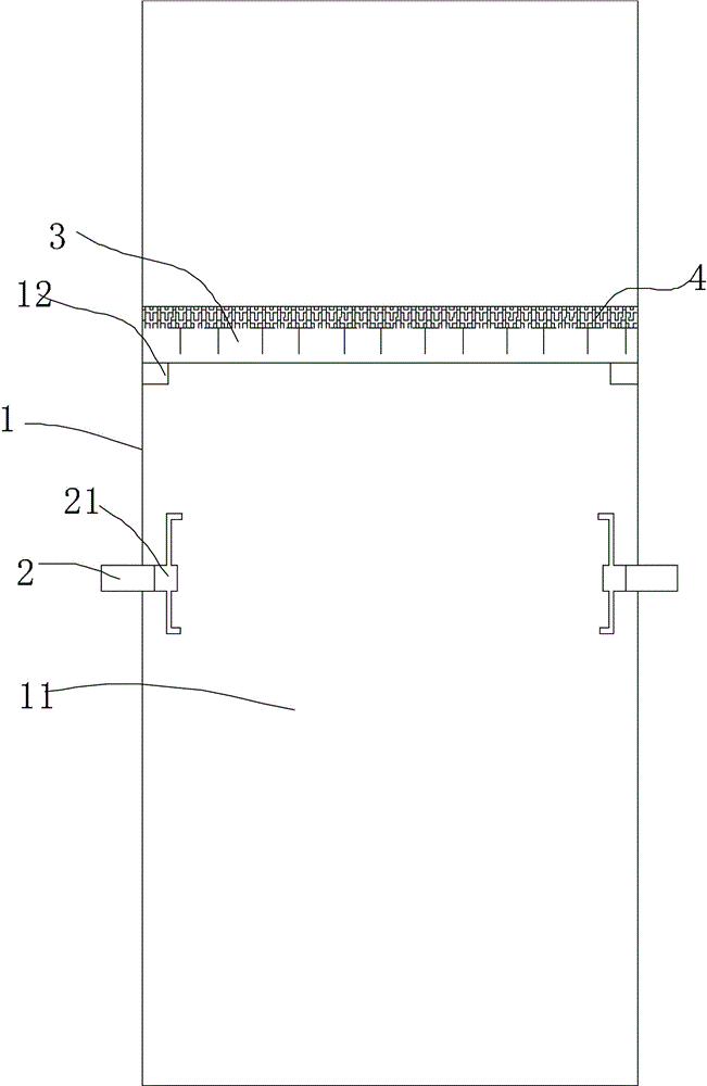
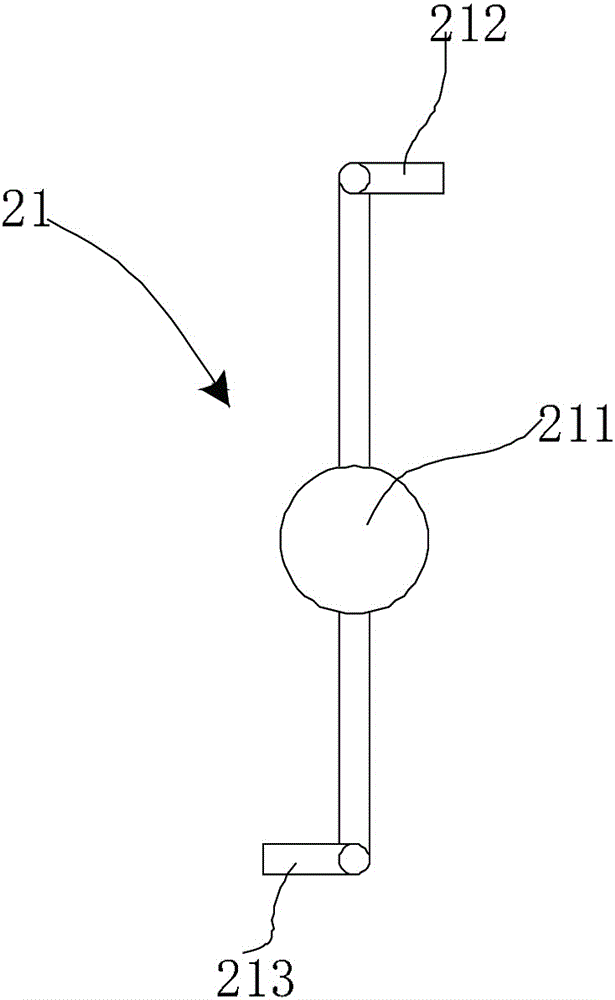
[0013] Such as Figures 1 to 2 As shown, a high-efficiency denitrification device includes a casing 1, and a channel 11 for flue gas to pass through and an injector 2 for injecting ammonia gas are arranged in the casing 1. Ejector comprises main body and the shower head 21 that is rotatably connected on the main body, and shower head 21 comprises tap 211 and nozzle 212,213, and nozzle 212,213 is welded on the tap 211, and tap 211 is rotatably connected on the trunk, and nozzle 212,213 Spray in a tangential direction.

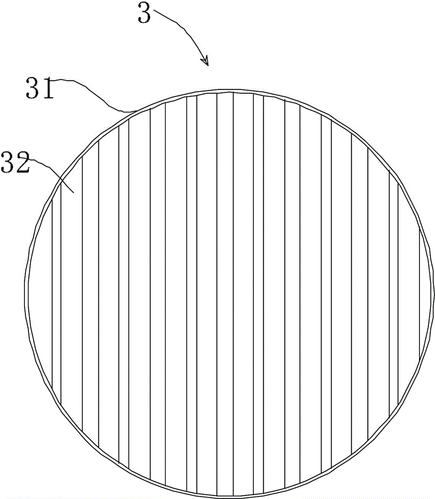
[0014] An annular retaining ring 12 is arranged at a position above the injector 2 in the channel 11, and a spoiler 3 is arranged on the retaining ring 12, and the spoiler 3 includes a fixed plate 31 and a T-shaped plate 32 made of metal, The fixing plate 31 is an annular baffle plate, and the T-shaped plate includes two ...


PUM


Abstract

The invention discloses high-efficiency denitrification equipment. The high-efficiency denitrification equipment comprises a shell, wherein the shell is internally provided with a channel through which flue gas passes and an injector for injecting ammonia gas; a circle of annular retainer ring is arranged at the position, located above a nozzle, in the channel; one spoiler is arranged on the retainer ring; the spoiler comprises a fixed plate made of metal and a T-shaped plate; the fixed plate is one circle of annular baffle; the T-shaped plate comprises two metal plates which are vertical to each other; the end part of one metal plate is welded with the middle position of the other metal plate; the fixed plate is erected on the retainer ring; two ends of the T-shaped plate are fixed on the fixed plate; one layer of metal wire net plate is arranged above the retainer ring; and two ends of the metal wire net plate are connected with a power supply.

Description

technical field [0001] The invention relates to the technical field of denitrification, in particular to a catalyst-free denitrification device. Background technique [0002] In the general non-catalyzed denitrification scheme, the emission of nitrogen oxides (NOx) is reduced by adding denitrification agents such as liquid ammonia, ammonia gas or urea solution to the flue gas treatment process at 800-1100°C. It can reduce nitrogen oxides (NOx) to N2, but its denitrification efficiency is generally low, especially for large boilers. The main reason is that the denitrification efficiency is affected by the following factors: 1) The nitrogen oxides and the denitrification agent are not fully mixed in the combustion chamber; 2) The temperature distribution of the flue gas in the denitrification reaction area is uneven; therefore, many traditional SNCR methods can no longer Meets today's stringent requirements for NOx emissions from coal-fired boilers. [0003] Patent CN2011104...

Claims


Application Information

Patent Timeline
Patent Type & Authority Applications(China)
IPC IPC(8): B01D53/76B01D53/56
CPCB01D53/56B01D53/76B01D2259/122B01D2251/2062
Inventor 周海平陈洋陈佩玉李俊强
Owner SHANGHAI WISEBOND TECH
Why Eureka
Try Eureka