
Meat grinder

A meat grinder and meat grinder technology, applied in the field of meat grinder, can solve problems such as untimely supply of raw materials, affecting product processing quality, and low processing efficiency, and achieve the effects of shortened idle time, stable work, and high processing efficiency

Inactive Publication Date: 2017-02-22
SUNBY MACHINERY CO LTD
View PDF11 Cites 1 Cited by
  • Summary
  • Abstract
  • Description
  • Claims
  • Application Information

AI Technical Summary

Problems solved by technology

However, the existing meat grinder is prone to problems such as untimely supply of raw materials, affecting product processing quality, and low processing efficiency.

Method used


Image

  • Meat grinder
  • Meat grinder
  • Meat grinder

Examples


Embodiment 1

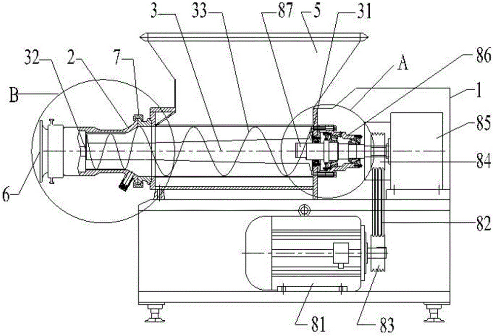
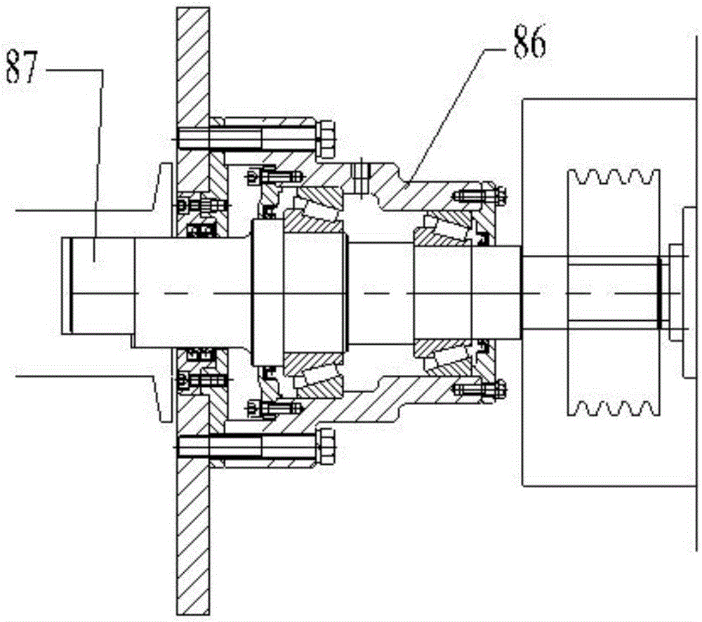
[0036] This embodiment provides a kind of meat grinder, such as figure 1 , 4 As shown, it includes a housing 1, a driving mechanism, a meat grinding cavity 2, a screw shaft 3, a meat grinding part 4, a feed port 5 and a discharge port 6. The upper part of the housing 1 is provided with a feed port 5, and the housing 1 One side is provided with a discharge port 6, and the inside of the housing 1 is located between the feed port 5 and the discharge port 6, and a meat grinding cavity 2 is provided. The meat grinding cavity 2 is provided with a screw shaft 3, and the screw shaft 3 includes a second One end 31 and the second end 32, the output end of the driving mechanism is connected with the first end 31 of the screw shaft 3; Connection, the diameter of the first end 31 of the screw shaft 3 is greater than the diameter of the second end 32 of the screw shaft 3 .

[0037] The first end 31 has a strong ability to swallow material when feeding, and the ability of the second end 32...

Embodiment 2

[0039] This embodiment is an embodiment further improved on Embodiment 1, which includes all the content of Embodiment 1, that is, the meat grinder provided in this embodiment includes all the structural features of Embodiment 1 meat grinder, and the improvements are:

[0040] Such as Figure 1-12 As shown, on the basis of the first embodiment, the diameter of the first end 31 of the screw shaft 3 in this embodiment is twice the diameter of the second end 32 of the screw shaft 3 .

[0041] The shell is 3 meters long, 1.4 meters wide and 2.1 meters high. Feeding port 5 is an inverted square prism type, the large end of feeding port 5 is located at the upper side, the length of the large end of feeding port 5 is 1546mm, the width of the large end of feeding port 5 is 1000mm, and the small The length of the end is 1000mm, the width of the small end of the feed port 5 is 420mm, and the height of the feed port 5 is 550mm.

[0042] The feed port 5 in this embodiment is much larger...


PUM


Abstract

The invention discloses a meat grinder, and belongs to the technical field of meat grinding devices. The meat grinder comprises a shell, a driving mechanism, a meat grinding cavity, a spiral shaft, a meat grinding part, a feed port and a discharge port; the feed port is formed in the upper part of the shell; the discharge port is formed in one side of the shell; the meat grinding cavity is formed between the feed port and the discharge port in the shell; the spiral shaft is arranged in the meat grinding cavity, and includes a first end and a second end; an output end of the driving mechanism is connected with the first end of the spiral shaft; the meat grinding part is arranged in the discharge port; the second end of the spiral shaft is connected with the meat grinding part; and the diameter of the first end of the spiral shaft is larger than the diameter of the second end of the spiral shaft. The first end of the spiral shaft is high in swallowing capacity during feeding; and the meat grinding capacity of the second end is lower than the feeding capacity of the first end, so that the meat grinder can always work with materials without generating idle or shortening the idle time, the conveying speed is stable, the work is stable, and the machining efficiency is high.

Description

technical field [0001] The invention relates to the technical field of meat mincers, in particular to a meat grinder. Background technique [0002] Meat grinder is a commonly used minced meat device in the production process of meat processing enterprises. It processes raw meat into granular meat fillings with different specifications according to different process requirements. It is widely used in various sausages, ham sausages, and luncheon meat. , meatballs, salty flavors, pet food and other meat products and other industries. However, existing meat grinders are prone to the problems of untimely supply of raw materials, affecting product processing quality, and low processing efficiency. Contents of the invention [0003] The object of the present invention is to provide a meat grinder with timely supply of raw materials and high processing efficiency, so as to solve the above-mentioned problems in the prior art. [0004] To achieve the above object, the present inve...

Claims


Application Information

Patent Timeline
Patent Type & Authority Applications(China)
IPC IPC(8): B02C18/30B02C18/38B02C23/02
CPCB02C18/301B02C18/38B02C23/02
Inventor 张百春王中秋杜红鹏
Owner SUNBY MACHINERY CO LTD
Learn More