Cleaning equipment and photovoltaic module cleaning system

A technology for cleaning equipment and photovoltaic panels, which is applied in photovoltaic modules, photovoltaic power generation, cleaning and flexible items, etc., can solve the problems of long cycle, large photovoltaic power station area, and high cost, and achieves a wide range of applications, simple and compact equipment structure, and cost. low effect

Inactive Publication Date: 2017-02-22
HANGZHOU PINNET TECH CO LTD
View PDF13 Cites 12 Cited by
  • Summary
  • Abstract
  • Description
  • Claims
  • Application Information

AI Technical Summary

Problems solved by technology

Generally, photovoltaic power plants have a large area, and most of them use m

Method used


Image

  • Cleaning equipment and photovoltaic module cleaning system
  • Cleaning equipment and photovoltaic module cleaning system
  • Cleaning equipment and photovoltaic module cleaning system

Examples


Embodiment 1

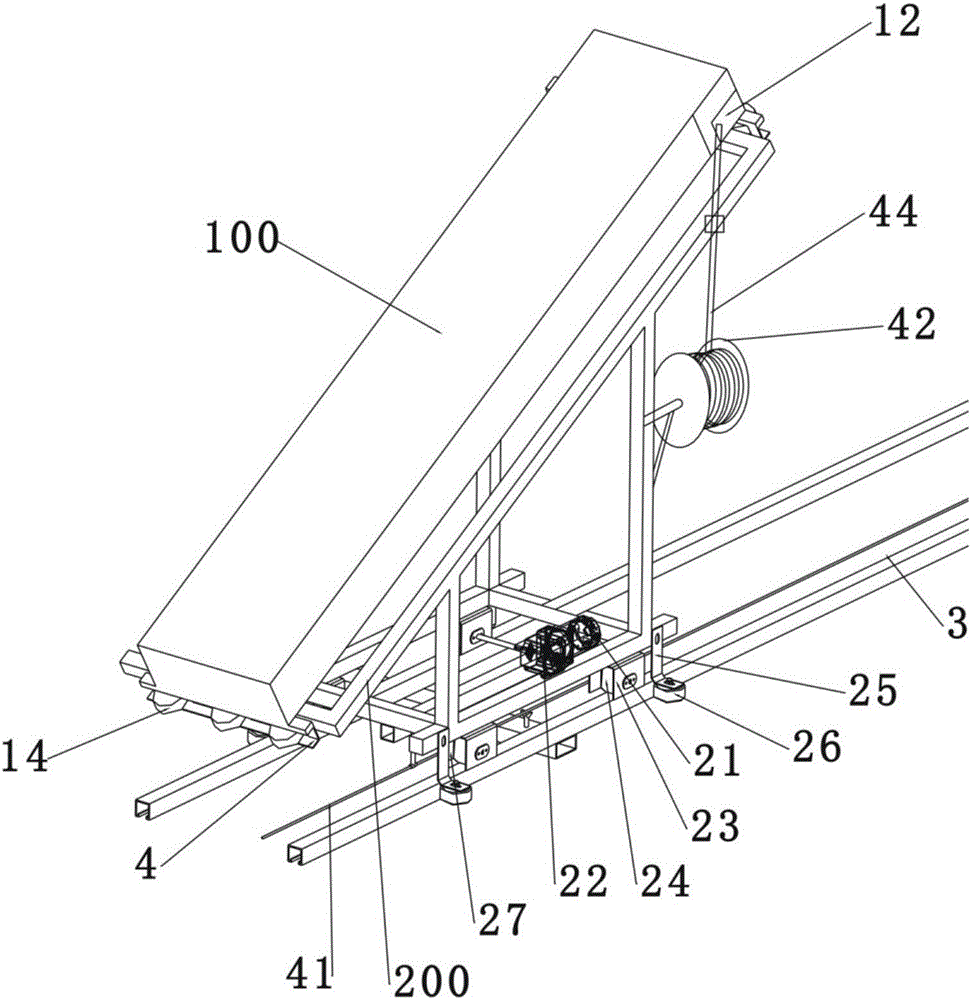
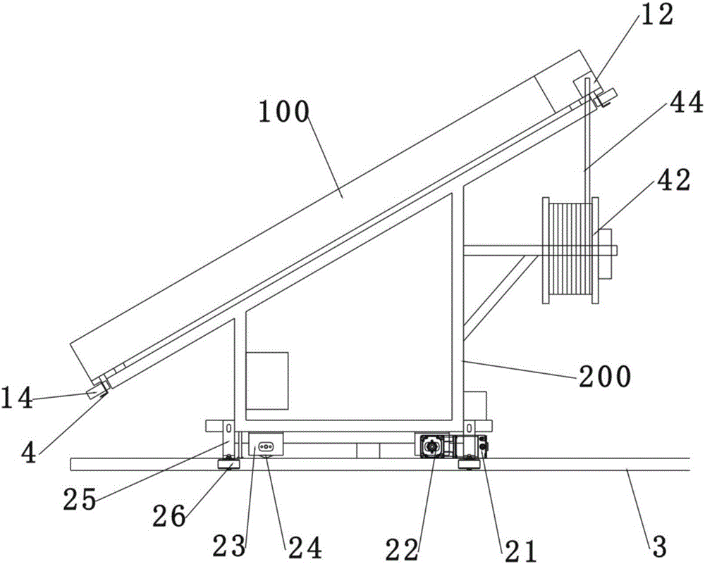
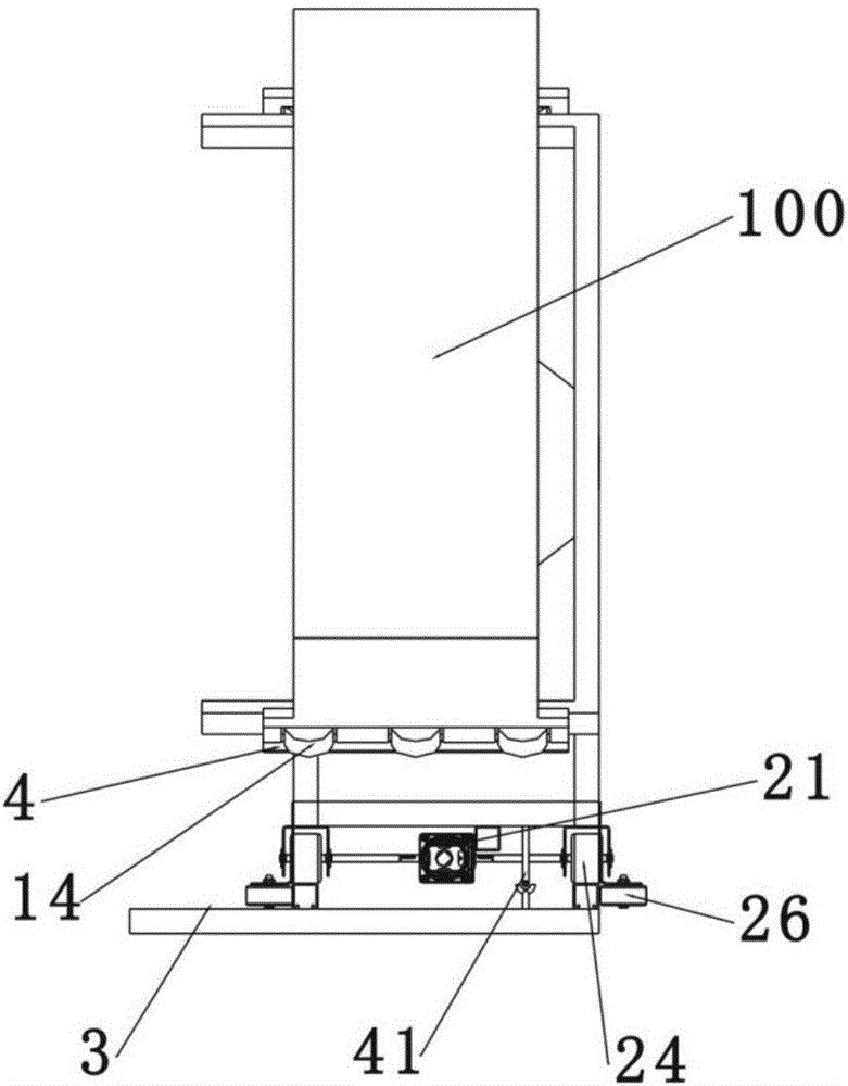
[0028] The technical scheme adopted by the present invention involved in the present invention is a cleaning device, including a cleaning machine 1, a mobile dock 2, a guide rail 3 and a control system, the mobile dock 2 is used to carry the cleaning machine 1, and the control system Under the control of the control system, the cleaning machine 1 can move with the mobile dock 2 under the control of the control system.

[0029] The mobile wharf 2 includes a loading frame 200, a first driving device, and a first traveling mechanism. The cleaning machine 1 is firmly placed on the loading frame 200, and the loading frame 200 is at a certain inclination angle, which is consistent with the array Photovoltaic panels 500 are consistent. The cleaning machine 1 can be fastened on the loading frame 200 through the clamping block 4 . The first driving device includes a transmission-connected first motor 21 and a reduction box 22. During operation, the first motor 21 drives the reduction ...

Embodiment 2

[0033] A photovoltaic module cleaning system using the cleaning equipment in Embodiment 1, the array photovoltaic panel 500 is an m*n matrix, m and n are both positive integers, Figure 4Shown in is the matrix of m=1, n=3. During work, the guide rail 3 is placed on one side of the array photovoltaic panel 500, the mobile dock 2 is placed above the guide rail 3, and the cleaning machine 1 is loaded on the carrier 200 of the mobile dock 2 Above all, the inclination angle of the carrier frame 200 should be basically consistent with the inclination angle of the array photovoltaic panel 500, so as to make the cleaning cleaner without hindering the operation of the cleaning machine. A certain tolerance is allowed for the inclination angle. When there is an angle tolerance, it is necessary to properly adjust the height of the carrier frame 200 and then adjust the height of the cleaning machine 1 to ensure that the operation does not get stuck. The cleaning machine 1 is on the upper ...


PUM


Abstract

The invention discloses cleaning equipment and a photovoltaic module cleaning system. The cleaning equipment comprises a cleaning machine, a moving wharf, guide rails and a control system. The moving wharf is used for bearing the cleaning machine and controlled by the control system to advance along the guide rails. The cleaning machine is controlled by the control system to be capable of moving on the moving wharf. The photovoltaic module cleaning system comprises array photovoltaic panels, the array photovoltaic panels are in an m*n matrix, and m and n are each a positive integer. The guide rails are located on one side of the array photovoltaic panels. The moving wharf is located above the guide rails. The cleaning machine is loaded on a bearing frame of the moving wharf and does back and forth movement on the array photovoltaic panels through a walking mechanism. The cleaning equipment and the photovoltaic module cleaning system are simple and compact in structure, high in automation degree and cleaning efficiency and stable in operating, and the problems that in current manual cleaning, time and labor are consumed, and efficiency is low are solved.

Description

technical field [0001] The invention relates to cleaning equipment for a photovoltaic power station, in particular to a cleaning equipment and a photovoltaic module cleaning system. Background technique [0002] The main power generation equipment of the solar photovoltaic power station is the solar photovoltaic panel, and the power generation of the solar photovoltaic panel depends on the intensity of the incident sunlight. Array photovoltaic panels are all installed in the open air. Natural wind, sand, dust, industrial pollutants, etc. cover the surface of the panels, which will greatly affect the absorption of light. According to statistics, the loss can account for 5-5% of the total solar power generation. 8%, or even more. Therefore, it is necessary to regularly clean the surface of the solar panel at an appropriate time, so as to reduce dust accumulation and improve the efficiency of the power station. Generally, photovoltaic power plants have a large area, and most ...

Claims


Application Information

Patent Timeline
IPC IPC(8): B08B11/04B08B1/00H02S40/10
CPCB08B1/00B08B11/04H02S40/10Y02E10/50
Inventor 何春涛尹立胜赵思波王龙梁中堂蒋邦友马林朱文平曲新春
Owner HANGZHOU PINNET TECH CO LTD
Why Eureka
Try Eureka