Ash removing device and method for fiber drawing furnace

A wire drawing furnace and optical fiber technology, which is applied in the field of optical fiber drawing, can solve problems such as equipment shutdown and optical fiber processing quality, and achieve the effects of reducing the probability of contact, improving the processing environment, and setting up reasonably

Active Publication Date: 2017-02-22
SICHUAN LEFEI OPTOELECTRONICS TECH CO LTD
View PDF7 Cites 8 Cited by
  • Summary
  • Abstract
  • Description
  • Claims
  • Application Information

AI Technical Summary

Problems solved by technology

This will cause equipment downtime, and the quality of fiber processing m

Method used


Image

  • Ash removing device and method for fiber drawing furnace
  • Ash removing device and method for fiber drawing furnace
  • Ash removing device and method for fiber drawing furnace

Examples


Embodiment Construction

[0019] In order to better understand the present invention, the present invention will be further described below in conjunction with the accompanying drawings and embodiments.

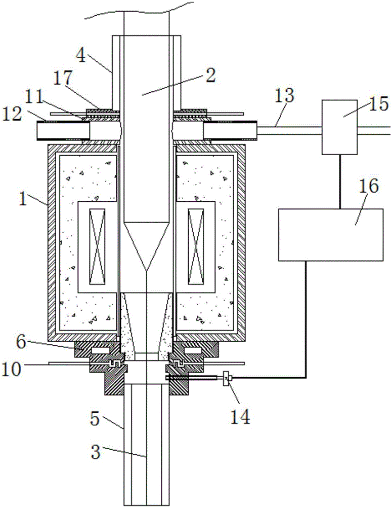
[0020] Such as figure 1 As shown, a dust removal device for an optical fiber drawing furnace includes a gas introduction device 6, a negative pressure suction device and a pressure control device. The top of the gas introduction device is nested with the bottom of the drawing furnace 1, and the bottom is nested with the lower furnace tube 5. Then, the negative pressure suction device is arranged on the top of the wire drawing furnace and communicates with the upper furnace tube 4. The pressure control device includes a pressure detector, a PLC controller 16 and a pressure regulator. The pressure detector is arranged in the gas introduction device, and the pressure regulator Set in the negative pressure suction device, the input end of the PLC controller is connected with the pressure detector, and the...


PUM


Abstract

The invention provides an ash removing device and method for a fiber drawing furnace. The ash removing device comprises a gas guide-in device, a negative pressure suction device and a pressure control device, wherein the top of the gas guide-in device is connected with the bottom of the fiber drawing furnace in a sleeving manner; the bottom of the gas guide-in device is connected with a lower furnace tube in a sleeving manner; the negative pressure suction device is arranged on the top of the fiber drawing furnace and communicates with an upper furnace tube; the pressure control device comprises a pressure detector, a PLC and a pressure adjuster; the pressure detector is arranged in the gas guide-in device; the pressure adjuster is arranged in the negative-pressure suction device; an input end of the PLC is connected with the pressure detector; and an output end of the PLC is connected with the pressure adjuster. By the ash removing device and method for the fiber drawing furnace, ash removing efficiency of the fiber drawing furnace can be improved, a fiber processing environment is improved, and the period of stopping for ash removal of the fiber drawing furnace is prolonged.

Description

technical field [0001] The invention belongs to the technical field of optical fiber drawing, and in particular relates to an ash removal device and method for an optical fiber drawing furnace. Background technique [0002] Optical fiber drawing is a process in which an optical fiber preform is heated and melted at a high temperature in a drawing furnace to be drawn into an optical fiber. The insulation layer and the heating element in the wire drawing furnace mostly use graphite substrates. During the wire drawing process, an inert gas is input into the wire drawing furnace to prevent the oxidation of the optical fiber preform rod and the graphite substrate. In actual production, graphite substrates and optical fiber preforms still undergo physical and chemical reactions in an inert gas environment to generate furnace ash. These furnace ashes will spread into the drawing environment, which will harm the human body and pollute the environment. When the furnace dust accumul...

Claims


Application Information

Patent Timeline
IPC IPC(8): B08B15/04C03B37/029
CPCY02P40/57B08B15/04C03B37/029
Inventor 汪杰范明峰杨武雷高清曹蓓蓓
Owner SICHUAN LEFEI OPTOELECTRONICS TECH CO LTD
Why Eureka
Try Eureka