Casting mold cooling structure

A technology for cooling structures and casting molds, which is applied in the direction of manufacturing tools, casting molding equipment, casting molds, etc., and can solve problems such as time-consuming and low production efficiency

Inactive Publication Date: 2017-02-22
重庆淬智机械有限公司
View PDF0 Cites 2 Cited by
  • Summary
  • Abstract
  • Description
  • Claims
  • Application Information

AI Technical Summary

Problems solved by technology

If you wait for the mold and the blank to cool naturally, it will take a very long time, resulting in low production efficiency

Method used


Image

  • Casting mold cooling structure

Examples


Embodiment 1

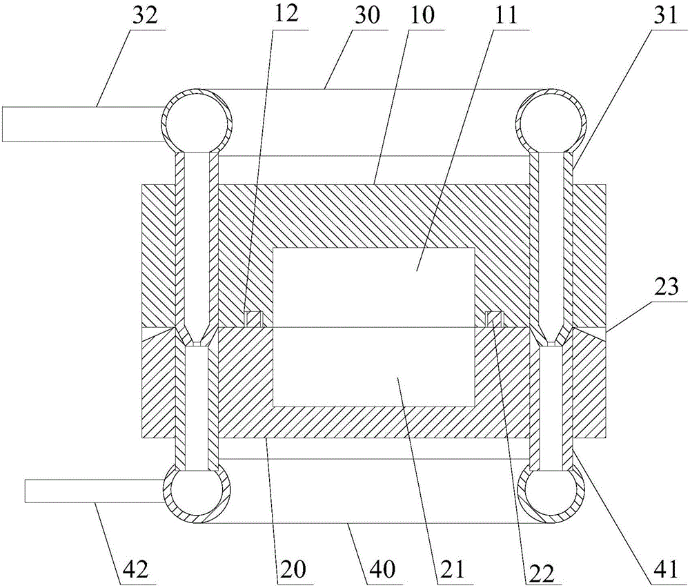
[0030] Such as figure 1 As shown, the casting mold cooling structure includes an upper mold 10, a lower mold 20, a water inlet ring pipe 30, a water inlet straight pipe 31, a water inlet pipe 32, a water return ring pipe 40, a water return straight pipe 41 and a water return pipe 42;

[0031] The bottom surface of the upper mold 10 is provided with an upper mold cavity 11; the top surface of the lower mold 20 is provided with a lower mold cavity 21 matching the upper mold cavity 11;

[0032] A plurality of straight water inlet pipes 31 run through the upper mold 10 from top to bottom, and are arranged around the upper mold cavity 11; the lower ends of the straight water inlet pipes 31 are located below the bottom surface of the upper mold 10; The lower end of the straight water inlet pipe 31 is tapered with a diameter gradually decreasing from top to bottom; The upper water inlet ring pipe 30 is connected; the water inlet pipe 32 is connected with the water inlet ring pipe 30...


PUM


Abstract

The invention discloses a casting mold cooling structure which comprises an upper die, a lower die, a water inlet ring pipe, water inlet straight pipes, a water inlet pipe, a return water ring pipe, return water straight pipes and a return water pipe. The plurality of water inlet straight pipes penetrate the upper die and are arranged around an upper die cavity; the lower ends of the water inlet straight pipes are in a cone shape with the diameter gradually reduced from top to bottom, the upper ends of the water inlet straight pipes are connected with the water inlet ring pipe above the top surface of the upper die, and the water inlet pipe is connected with the water inlet ring pipe. The plurality of return water straight pipes penetrate the lower die and are arranged around an lower die cavity. The end faces of the upper ends of the return water straight pipes are level with the top surface of the lower die, the upper ends of the return water straight pipes are conical, the lower ends of the return water straight pipes are located below the bottom surface of the lower die and connected with the return water ring pipe below the bottom surface of the lower die, and the return water pipe is connected with the return water ring pipe. The upper die and the lower die are buckled with each other, the bottom surface of the upper die adheres to the top surface of the lower die, and the peripheral surfaces of the lower ends of the water inlet straight pipes adhere to the inner circumferences of the upper ends of the return water straight pipes. According to the casting mold cooling structure, a die and workblank can be quickly cooled.

Description

technical field [0001] The invention relates to the field of casting, in particular to a casting mold cooling structure. Background technique [0002] Many auto parts need to be manufactured by casting process, such as car wheels. During casting, the metal liquid is injected into the casting mold, and after the metal liquid is cooled and formed in the casting mold, the solidified part blank is obtained, and the finished auto parts can be obtained after the blank is taken out for finishing. In order to take out the solidified component blank from the mold, it is usually necessary to wait for the mold and the blank to cool to a certain temperature before performing the demoulding operation. If you wait for the mold and the blank to cool naturally, it will take a very long time, resulting in low production efficiency. Contents of the invention [0003] The object of the present invention is to overcome the above-mentioned problems of the prior art and provide a casting mold...

Claims


Application Information

Patent Timeline
IPC IPC(8): B22D15/00B22D27/04B22C9/06
CPCB22D15/00B22C9/065B22D27/04
Inventor 陈和平
Owner 重庆淬智机械有限公司
Why Eureka
Try Eureka