
Work fixture on laser cutting device

A technology of laser cutting and tooling fixtures, applied in the field of tooling fixtures, can solve the problems of inability to guarantee the flatness and stability of metal sheets, inconvenient manual cleaning of waste materials, low cutting quality, etc., and achieves simple structure, convenient cutting, and high cutting quality. Effect

Active Publication Date: 2017-02-22
天润智能科技(昆山)有限公司
View PDF6 Cites 2 Cited by
  • Summary
  • Abstract
  • Description
  • Claims
  • Application Information

AI Technical Summary

Problems solved by technology

[0007] For this reason, the technical problem to be solved by the present invention is that the clamping process of the clamping device used for laser cutting in the prior art is time-consuming and laborious, the work efficiency is low, the flatness and stability of the metal sheet cannot be guaranteed, the cutting quality is low, and the The temperature of the waste material is high, and it is inconvenient to manually clean up the waste material, so a tooling fixture for laser cutting equipment is proposed

Method used


Image

  • Work fixture on laser cutting device
  • Work fixture on laser cutting device
  • Work fixture on laser cutting device

Examples


Embodiment Construction

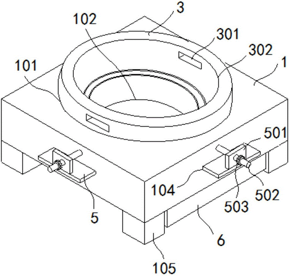
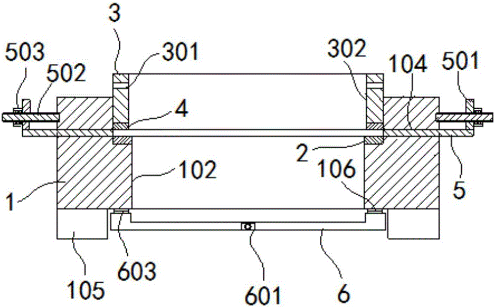
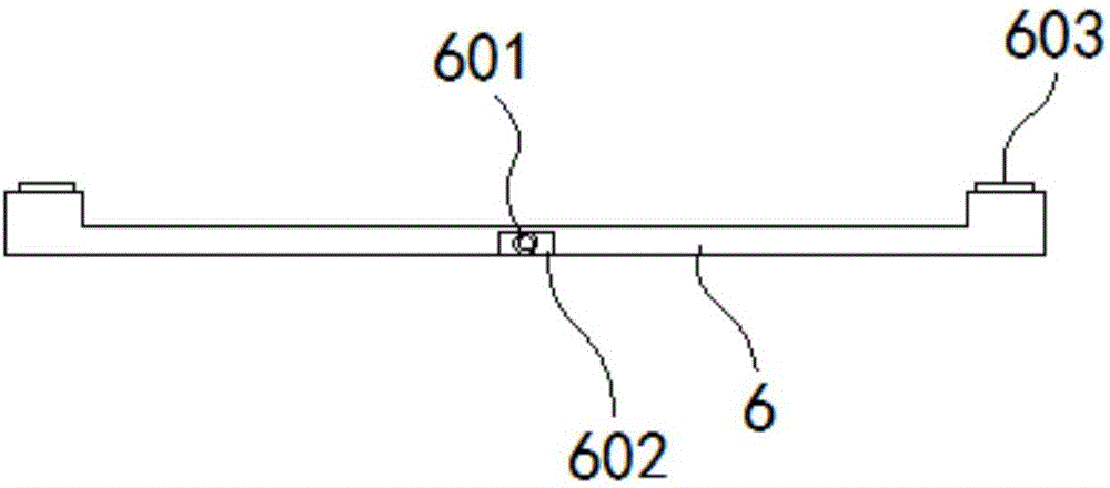
[0030] Such as figure 1 , figure 2 As shown, the fixture of the laser cutting equipment of the present invention includes:

[0031] Base 1, a circular sunken platform 101 is formed on the base 1, a through hole 102 penetrating the bottom surface of the base 1 is formed in the center of the sunken platform 101, and a through hole 102 is formed on the side wall of the sunken platform 101 through the base. 1 short groove 104 in the outer wall. Four corners of the lower end surface of the base 1 are respectively provided with fixing blocks 105 , and the base 1 is fixed on the machine platform or the ground through the fixing blocks 105 .

[0032] The first magnetic chuck 2 is fixedly arranged on the upper surface of the countertop 101 . The lower end surface of the short slot 104 is flush with the upper end surface of the first magnetic chuck 2 .

[0033] The fixed seat 3, the fixed seat 3 is a circular fixed seat, the fixed seat 3 is inserted into the sinking platform 101 of...


PUM


Abstract

The invention discloses a work fixture on a laser cutting device. The work fixture on the laser cutting device comprises a base, a first magnetic sucker, a fixing base, a second magnet sucker, a positioning block and a material discharging case. By the arrangement of the magnetic suckers arranged on a cushion cap and the fixing base, a metal plate can be conveniently clamped and fixed to guarantee flatness and stability of the metal plate, and cutting quality is high; by the arrangement of the positioning block, the position of the metal plate can be adjusted to facilitate cutting, and processing quality is further improved; through the material discharging case arranged on the lower part of the base, waste materials after processing can be conveniently removed and recycled. The work fixture on the laser cutting device is simple in structure, convenient to operate, high in processing efficiency and high in processing quality, and is suitable for large-scale production.

Description

[0001] Technical field: [0002] The invention belongs to the technical field of laser cutting equipment, and in particular relates to a tooling fixture on the laser cutting equipment. [0003] Background technique: [0004] Laser cutting is the use of high-power-density laser beams to irradiate materials, so that the materials are quickly heated to the vaporization temperature, and evaporate to form holes. As the beam moves to the material, the holes continuously form narrow (such as about 0.1mm) slits, and the process is completed. Cutting of material. Laser cutting is one of the thermal cutting methods. Laser cutting can be divided into four categories: laser vaporization cutting, laser melting cutting, laser oxygen cutting, and laser scribing and controlled fracture. It has the advantages of good cutting quality, high cutting efficiency, and fast cutting speed. It is a commonly used thermal cutting method for some sheet metal parts. [0005] In the prior art, the positio...

Claims


Application Information

Patent Timeline
Patent Type & Authority Applications(China)
IPC IPC(8): B23K26/70B23K37/04
CPCB23K26/702B23K37/0408B23K2101/18
Inventor 叶芳
Owner 天润智能科技(昆山)有限公司
Learn More