Magnetic suspension gantry processing center

A machining center and magnetic levitation technology, used in metal processing equipment, metal processing mechanical parts, manufacturing tools, etc., can solve the problems of low accuracy and reliability, low degree of automation, cumbersome processes, etc., and achieve stable head movement and high processing accuracy. , the effect of expanding the selection

Active Publication Date: 2017-02-22
福建省正丰数控科技有限公司
View PDF5 Cites 14 Cited by
  • Summary
  • Abstract
  • Description
  • Claims
  • Application Information

AI Technical Summary

Problems solved by technology

[0002] With the continuous development of science and technology, smart products such as mobile phones, computers, and LCD TVs are more and more popular in daily life. Mobile phone casings, LCD TV frames, etc. are usually used to achieve the comfort and aesthetics of such products. The material is changed from the early ABS, PC, PPO engineering material shells to aluminum, magnesium, stainless steel and other alloy shells, and the application requirements are realized by milling, drilling and tapping, and mirror processing of aluminum, magnesium, stainless steel and other alloy sheets. The processing process of the shell involves rough milling, fine milling, drilling and tapping, and high-gloss, so many product parts need to use many types of high-precision processing machine tools. At present, common 3C product processing machine tools are tapping drilling machines, engraving and milling machines, etc., targeted Strong, one piece of equipment can only be used for a single processing process
Therefore, the same part requires multiple processes, multiple equipment, multiple disassembly and assembly, and the process is cumbersome, resulting in low precision reliability, low automation, and troublesome maintenance.

Method used


Image

  • Magnetic suspension gantry processing center
  • Magnetic suspension gantry processing center
  • Magnetic suspension gantry processing center

Examples


Embodiment Construction

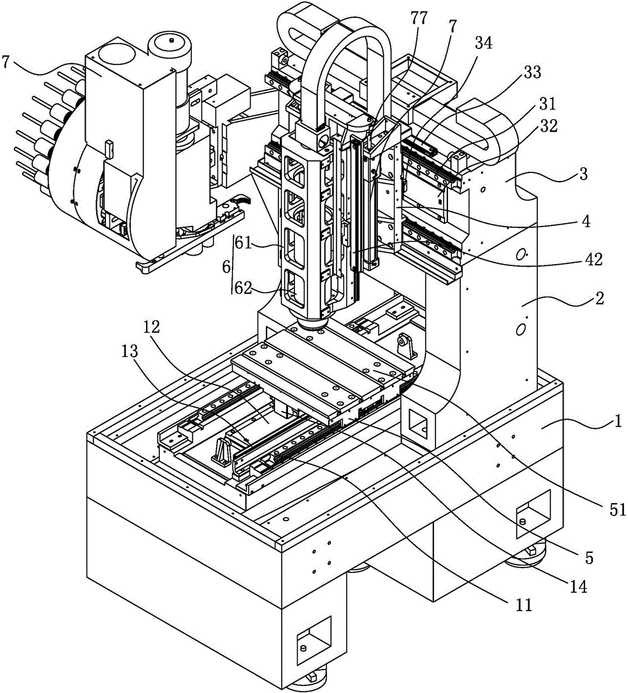
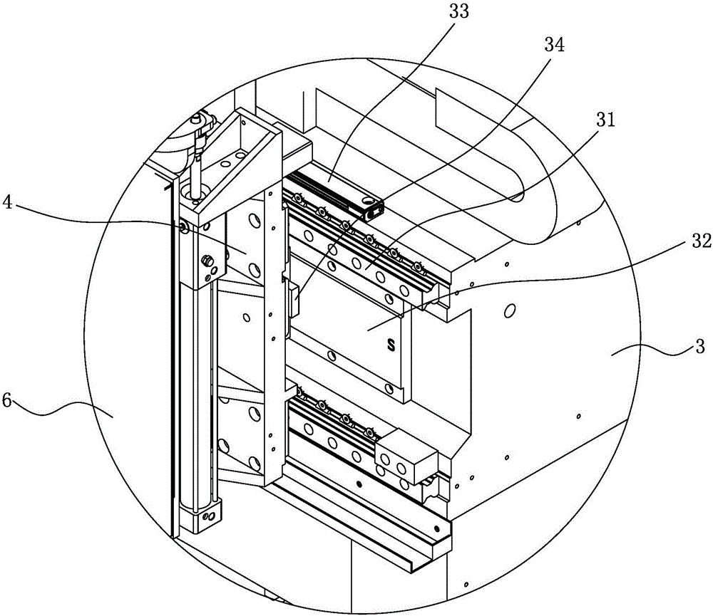
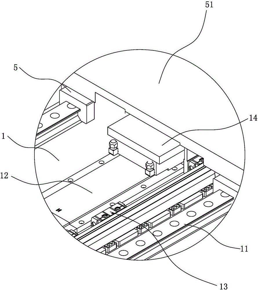
[0027] Such as Figure 1 to Figure 6 As shown, the maglev gantry machining center includes a base 1, two uprights 2 arranged at intervals on the base 1, a crossbeam 3 arranged between the two uprights 2, a tool magazine 10 arranged on one side of the crossbeam 3, and a ground that can move horizontally and horizontally. The first sliding seat 4 arranged on the crossbeam 3, the second sliding seat 5 arranged on the base 1 that can move vertically and horizontally, the machine head mounting frame 63 that can be moved up and down on the first sliding seat 4, and installed on the The machine head 6 on the machine head mounting frame 63, the object stage 51 that is rotatably arranged on the second slide seat 5, is arranged between the second slide seat 5 and the object stage 51 for driving the object stage 51 to rotate The first DD motor, the X-axis moving mechanism arranged between the beam 3 and the first sliding seat 4, the Y-axis moving mechanism arranged between the base 1 and...


PUM


Abstract

The invention provides a magnetic suspension gantry processing center. The magnetic suspension gantry processing center comprises a base, two upright posts oppositely arranged on the base at intervals, a cross beam arranged between the two upright posts, a first sliding seat arranged on the cross beam, capable of transversely and horizontally moving, a second sliding seat arranged on the base, capable of longitudinally and horizontally moving, a machine head mounting rack arranged on the first sliding seat, capable of moving in a liftable manner, a machine head mounted on the machine head mounting rack, an object carrying table rotatably arranged on the second sliding seat, a first DD motor which is arranged between the second sliding seat and the object carrying table and is used for driving the object carrying table to rotate, an X-axis moving mechanism arranged between the cross beam and the first sliding seat, a Y-axis moving mechanism arranged between the base and the second sliding seat, a Z-axis moving mechanism arranged between the first sliding seat and the machine head mounting rack, and a control device connected with the X-axis moving mechanism, the Y-axis moving mechanism, the Z-axis moving mechanism and the first DD motor. According to the magnetic suspension gantry processing center, multiple technologies can be achieved, the precision reliability is high, the automation degree is high, and the maintenance is convenient.

Description

technical field [0001] The invention relates to a magnetic levitation gantry processing center. Background technique [0002] With the continuous development of science and technology, smart products such as mobile phones, computers, and LCD TVs are more and more popular in daily life. Mobile phone casings, LCD TV frames, etc. are usually used to achieve the comfort and aesthetics of such products. The material is changed from the early ABS, PC, PPO engineering material shells to aluminum, magnesium, stainless steel and other alloy shells, and the application requirements are realized by milling, drilling and tapping, and mirror processing of aluminum, magnesium, stainless steel and other alloy sheets. The processing process of the shell involves rough milling, fine milling, drilling and tapping, and high-gloss, so many product parts need to use many types of high-precision processing machine tools. At present, common 3C product processing machine tools are tapping drilling ...

Claims


Application Information

Patent Timeline
Patent Type & Authority Applications(China)
IPC IPC(8): B23P23/02B23Q1/25B23Q1/34B23Q11/00B23Q1/01
CPCB23P23/02B23Q1/015B23Q1/25B23Q1/34B23Q11/001
Inventor 陈志明何轸炎谢进义王琦
Owner 福建省正丰数控科技有限公司
Why Eureka
Try Eureka