
Electric main shaft based on dynamic-pressure sliding bearings

A technology of sliding bearings and electric spindles, applied in electromechanical devices, driving devices, electrical components, etc., can solve problems such as limited carrying capacity, achieve high load capacity, high precision, and improve service life

Active Publication Date: 2017-02-22
CHANGZHOU INST OF MECHATRONIC TECH
View PDF5 Cites 7 Cited by
  • Summary
  • Abstract
  • Description
  • Claims
  • Application Information

AI Technical Summary

Problems solved by technology

The traditional electric spindle is mainly based on the design concept of rolling bearings, which limits the further increase of its speed and limited carrying capacity.

Method used


Image

  • Electric main shaft based on dynamic-pressure sliding bearings
  • Electric main shaft based on dynamic-pressure sliding bearings
  • Electric main shaft based on dynamic-pressure sliding bearings

Examples


Embodiment Construction

[0016] In order to make the content of the present invention more clearly understood, the present invention will be further described in detail below based on specific embodiments and in conjunction with the accompanying drawings.

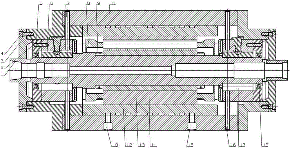
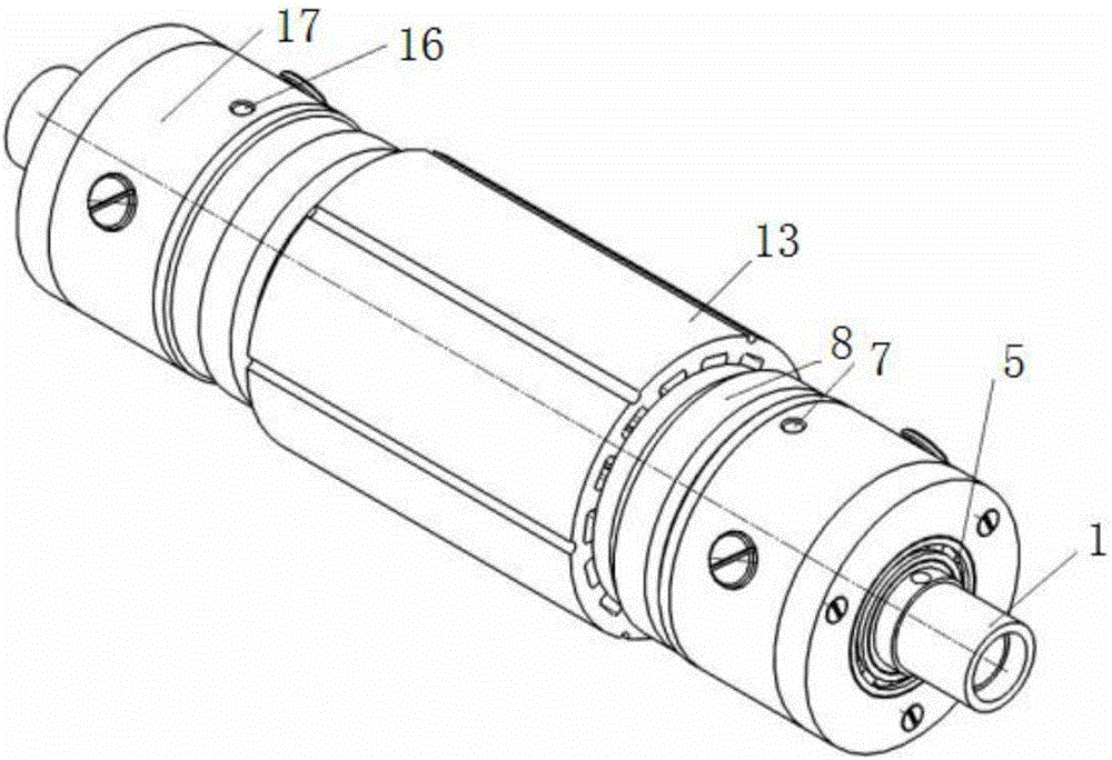
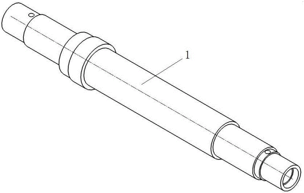
[0017] Such as figure 1 , figure 2 , image 3 As shown, an electric spindle based on a hydrodynamic sliding bearing includes an electric spindle housing 11, a main shaft 1, a motor, a lubrication and a cooling system, and the front and rear ends of the main shaft 1 are respectively equipped with a front hydrodynamic sliding bearing 6 and a rear The hydrodynamic sliding bearing 17, the front and rear hydrodynamic sliding bearings, the electric spindle housing 11, and the bearing end caps 3 located at both ends of the electric spindle housing 11 together form an integral sealed cavity, and the motor is installed on the front hydrodynamic sliding bearing 6 and Between the rear hydrodynamic sliding bearings 17, the motor rotor 14 is fixedly connecte...


PUM


Abstract

The invention discloses an electric main shaft based on dynamic-pressure sliding bearings. The electric main shaft comprises an electric main shaft shell, a main shaft, a motor and a lubricating and cooling system, wherein a front liquid dynamic-pressure sliding bearing and a back liquid dynamic-pressure sliding bearing are arranged at the front part and back end of the main shaft respectively; a rotor of the motor is fixedly connected with the main shaft and drives the main shaft to rotate; the lubricating and cooling system comprises a front nozzle, a back nozzle and a cooling jacket; the front nozzle communicates with the front liquid dynamic-pressure sliding bearing and penetrates through the electric main shaft shell; the back nozzle communicates with the back liquid dynamic-pressure sliding bearing and penetrates through electric main shaft shell; and the cooling jacket is provided with a cooling oil passage, and a cooling oil inlet and a cooling oil outlet which communicate with the cooling oil passage. The invention breaks through a traditional electric main shaft design concept based on a rolling bearing, and provides the electric main shaft based on the dynamic-pressure sliding bearings, and the electric main shaft based on the dynamic-pressure sliding bearings can bear a higher rotating speed, so that the service life can be effectively prolonged; and the electric main shaft based on the dynamic-pressure sliding bearings can bear a greater load, thereby having the characteristics of high carrying capacity, high precision, compact structure and long service life.

Description

technical field [0001] The invention relates to an electric spindle based on a dynamic pressure sliding bearing, belonging to the technical field of electric spindles. Background technique [0002] A motorized spindle is an integral unit with a high-speed motor built into the spindle. The rotor of the motor drives the main shaft to rotate together, realizing mechatronics. This transmission unit, which eliminates common mechanical devices such as belt transmission and gear transmission, and realizes the "zero transmission" structure of machine tools, is more and more widely used in modern machine tool design. It has compact structure, high speed, small mass, rapid start and stop, and easy operation Stable features make it the preferred structure for high-speed spindles. However, the traditional electric spindle is mainly based on the design concept of rolling bearings, which limits the further increase of its rotational speed and limited carrying capacity. Contents of the...

Claims


Application Information

Patent Timeline
Patent Type & Authority Applications(China)
IPC IPC(8): B23Q5/04H02K9/19H02K5/167
CPCB23Q5/043H02K5/1672H02K9/19
Inventor 白颖
Owner CHANGZHOU INST OF MECHATRONIC TECH
Learn More