Punching machine for producing keyboard circuit

A keyboard circuit and punching machine technology, applied in metal processing, etc., can solve problems such as unsafe operation and work-related injuries, and achieve the effects of improving safety, reducing energy consumption, and improving processing efficiency

Inactive Publication Date: 2017-02-22
重庆淳祥电子科技有限公司
View PDF7 Cites 8 Cited by
  • Summary
  • Abstract
  • Description
  • Claims
  • Application Information

AI Technical Summary

Problems solved by technology

The shortcoming of this punching machine is: because in the prior art, when the staff is operating, it is necessary to place the hand directly under the pressing plate to place the semi-finished product, if the punching mechanism suddenly presses down when the staff places the semi-finished product, it will appear Injury at work, unable to work safely

Method used


Image

  • Punching machine for producing keyboard circuit
  • Punching machine for producing keyboard circuit
  • Punching machine for producing keyboard circuit

Examples


Embodiment 1

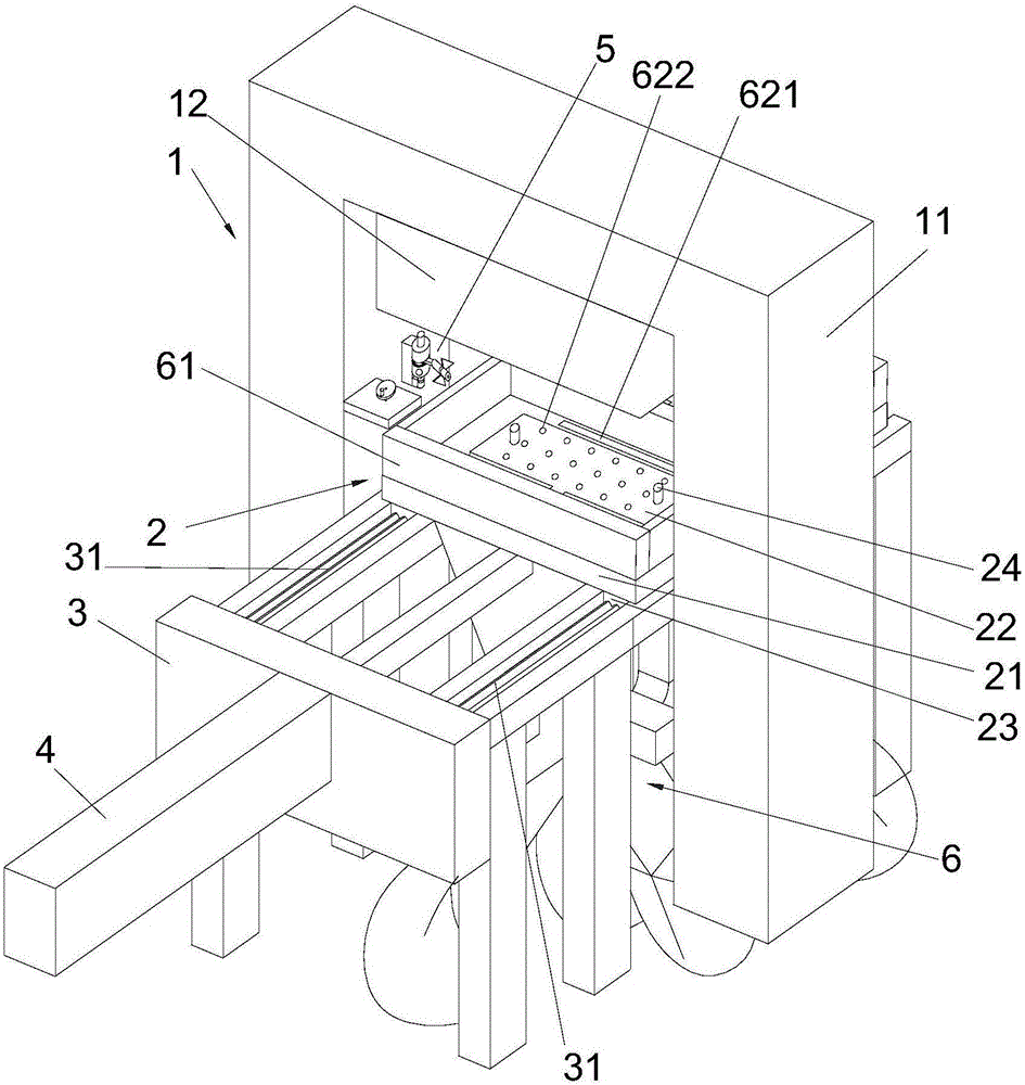
[0055] Such as figure 2 , image 3 as well as Figure 4 As shown, this embodiment proposes a punch press for producing keyboard circuits, including:

[0056] Punching mechanism 1, it comprises portal frame 11, and punching part 12 is installed on the portal frame 11, and the directly below punching part 12 is punching station;

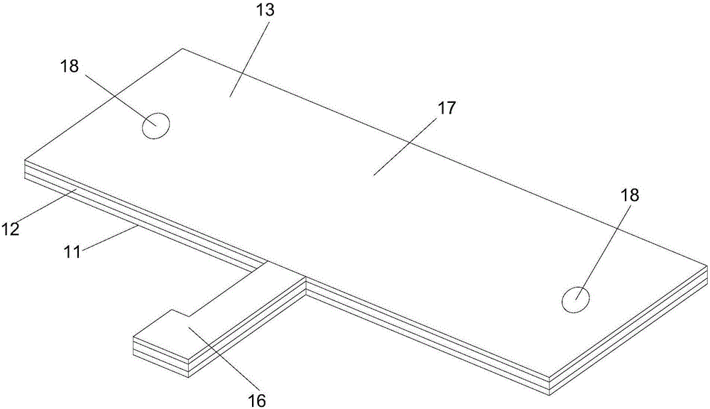
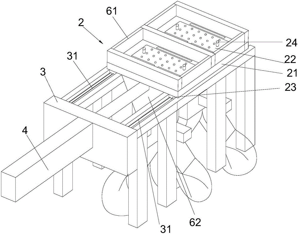
[0057] Station seat 2, it comprises bearing plate 21 and two placing molds 22, two placing molds 22 are installed on the carrying plate 21, two placing molds 22 are all used to place semi-finished products, and semi-finished products are placed on the output part of semi-finished products after two placing molds 22 Facing the same direction, four first wire pulleys 23 are arranged on the bottom surface of the bearing plate 21, and positioning columns 24 are arranged on the placement mold 22;

[0058] The support frame 3 has two slide rails 31 supported on its upper surface, the two slide rails 31 are parallel to each other and the two slide rails 3...

Embodiment 2

[0064] The difference between this embodiment and Embodiment 1 is only that: in order to avoid the punching mechanism 1 from crushing the semi-finished product due to rubber dust on the mold 22 when the semi-finished product is processed again, the present embodiment is provided with an air spray gun 5 .

[0065] Such as figure 2 , Figure 6 as well as Figure 9 As shown, the punch press for producing the keyboard circuit also includes an air jet gun 5, and the air jet gun 5 includes:

[0066] Mounting seat 51, it is arranged on the inner side of a gantry frame 11, is provided with drive cavity 511 in the mounting seat 51, and the first center shaft 512 that is positioned at vertical direction is erected on the bottom surface of driving cavity 511, and is provided with on the side of mounting seat 51 A slide groove 513 communicating with the drive chamber 511;

[0067] The air nozzle 52 is provided with an air connection hole (not shown) and an air outlet for communicating...

Embodiment 3

[0087] The difference between this embodiment and Embodiment 2 is that, in order to prevent the rubber shavings from being blown to the ground and pollute the working environment, this embodiment adds a rubber shavings storage mechanism.

[0088] Such as figure 2 As shown, in this embodiment, the punch press for producing the keyboard circuit also includes a rubber scrap storage mechanism 6, such as Figure 4 as well as Figure 5 As shown, the rubber scrap storage mechanism 6 includes:

[0089] Fence 61, it is arranged on two placement molds 22 besides, with every surrounding around placement mold 22;

[0090] Two receiving funnels 62, which are all arranged on the bottom surface of the bearing plate 21, each receiving funnel 62 is set opposite to a placing mold 22, and the receiving funnel corresponding to each is provided on the supporting plate 21 next to each placing mold 22 62 connected chip drop holes 621, and each placing mold 22 is also provided with a knife settin...


PUM


Abstract

The invention provides a punching machine for producing a keyboard circuit. The punching machine comprises a punching mechanism, a station base, a support frame, a transverse driving mechanism and a control box, wherein the punching mechanism includes a portal frame; a punching part is mounted on the portal frame; a punching station is rightly below the punching part; the station base includes a bearing plate and two placing molds; the two placing molds are mounted on the bearing plate, and are both used for placing semi-finished products; after the semi-finished products are placed on the two placing molds, output parts of the semi-finished products are towards the same one direction; four first wire wheels are arranged on the bottom surface of the bearing plate; two slide rails are supported on the upper surface of the support frame, are parallel to each other, and both penetrate through the portal frame; every two of the two first wire wheels are slidingly arranged in one slide rail; the transverse driving mechanism is mounted on the support frame, and an output part thereof is connected with the station base; and the punching mechanism and the transverse driving mechanism are electrically connected with the control box. The punching machine has the following beneficial effects: the punching machine prevents industrial accidents caused by sudden downward pressing of the pressing plate in placement of the semi-finished products.

Description

technical field [0001] The invention relates to a punch press for producing keyboard circuits, in particular to a punch press for producing keyboard circuits. Background technique [0002] Such as figure 1 As shown, in the keyboard production process, after the cutting die 11, the spacer 12 and the upper part 13 are pasted together (the cutting die 11, the spacer 12 and the upper part 13 are arranged in sequence from bottom to top), the surface of the output part needs to be Paste the reinforcing sheet, and paste the adhesive on the connection between the output part 16 and the main body part 17 to obtain a semi-finished product, and then need to use a punch to punch holes in the semi-finished product to prevent the internal circuit from sticking together after the silver paste is overheated. In the prior art, the punching machine includes: a working platform, which is supported by a support seat, a placing mold is arranged on the surface of the working platform, and the pl...

Claims


Application Information

Patent Timeline
Patent Type & Authority Applications(China)
IPC IPC(8): B26F1/02B26F1/14B26D7/18
CPCB26D7/1854B26F1/02B26F1/14
Inventor 王灯亮
Owner 重庆淳祥电子科技有限公司
Why Eureka
Try Eureka