
Preparation technology for honeycomb supporting structure

A technology of support structure and preparation process, which is applied to other household appliances, household appliances, household components, etc., can solve the problems of short service life, poor support effect and stability, etc., to reduce production costs, simple structure, and realize industrialization. production effect

Inactive Publication Date: 2017-02-22
成都柒柒家祥科技有限公司
View PDF9 Cites 0 Cited by
  • Summary
  • Abstract
  • Description
  • Claims
  • Application Information

AI Technical Summary

Problems solved by technology

[0004] The purpose of the present invention is to solve the problem that the existing supporting structures adopt the structure of horizontal bars or vertical bars, which leads to poor supporting effect and stability and short service life, and provides a preparation process of honeycomb support structure, through which The support structure produced not only has good support effect, good stability, and long service life, but also is simple to prepare, low in cost, and very convenient to transport

Method used


Image

  • Preparation technology for honeycomb supporting structure
  • Preparation technology for honeycomb supporting structure
  • Preparation technology for honeycomb supporting structure

Examples


Embodiment 1

[0033] A preparation process for a honeycomb support structure, comprising:

[0034] Step 1. The plastic is prepared into a plate-shaped substrate through an extruder. In order to facilitate the setting of creases in the later stage, and considering the requirements for support strength, the thickness of the substrate in the present invention is preferably 0.5-5mm, and the thickness of the substrate is preferably 3 mm in this embodiment. mm. In this embodiment, the plastic can be selected from ordinary plastic materials, such as PVC, PP, PE or XPS; it can also be preferably a material with a melting point above 200° C., such as PC and ABS.

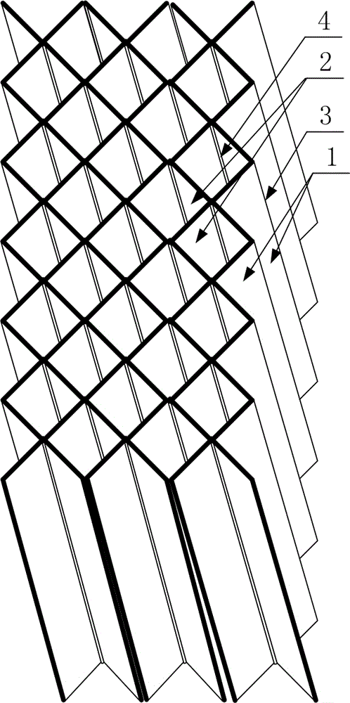
[0035] Step 2: Fold the plate-shaped base body by an edge-pressing machine to form creases, the base body can rotate along the creases, the folded creases are parallel to each other, and the distances between the creases are the same.

[0036] Step 3. Place more than two substrates in layers. When placing, the creases of two adjacent subs...

Embodiment 2

[0042] The difference between this embodiment and Embodiment 1 is that the settings of the creases in this embodiment are different, and the specific settings are as follows:

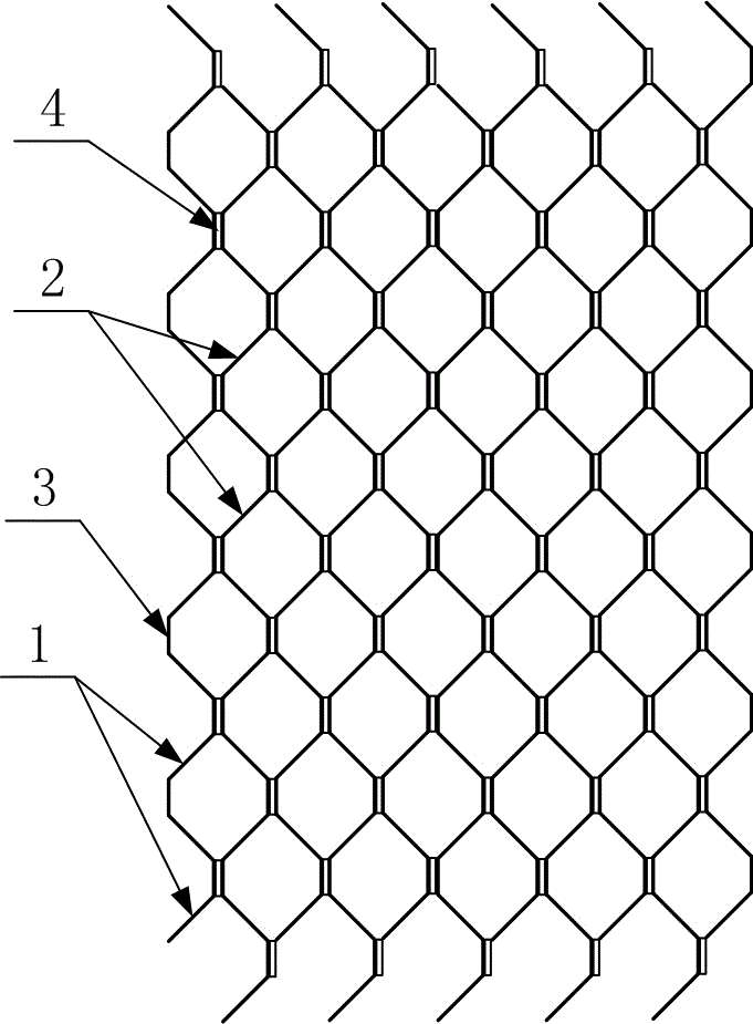
[0043] The creases on the substrate are all formed by two parallel folding lines, and a bonding plane is formed between the two folding lines, and the bonding plane is used to place bonding materials. Through the structure of this embodiment After setting, the finished product has a structure like figure 2 shown.

Embodiment 3

[0045] The difference between this embodiment and embodiment 2 is that the selection of the bonding material in this embodiment is different, and the specific settings are as follows:

[0046] In this embodiment, the bonding material does not use a thermal bonding material, but directly uses AB glue for fixing. When using AB glue for fixing, there is no need to reheat, and the AB glue can be dried naturally.


PUM

PropertyMeasurementUnit
melting pointaaaaaaaaaa
thicknessaaaaaaaaaa

Abstract

The invention discloses a preparation technology for a honeycomb supporting structure. The preparation technology for the honeycomb supporting structure includes the first step that plate-shaped base bodies with folding marks are prepared; the second step that two or more base bodies are placed in a stacked manner, during placement, the folding marks of every two adjacent base bodies overlap, every two adjacent base bodies are connected through a bonding material, and the bonding material is arranged on the folding marks; when the front face side of the folding marks on the same base body is provided with the bonding material, the back face side of the folding marks is not provided with the bonding material; and when the front face side of one of the folding marks on the same base body is provided with the bonding material, the front face side of the folding mark adjacent to the folding mark is not provided with the bonding material; and the third step that the base bodies which are placed in the stacked manner are bonded into a whole through the bonding material, and the finished product is prepared through cutting. The structure prepared through the preparation technology has the beneficial effects of being good in supporting effect, good in stability, long in service life, capable of saving the transporting and storing space and the like.

Description

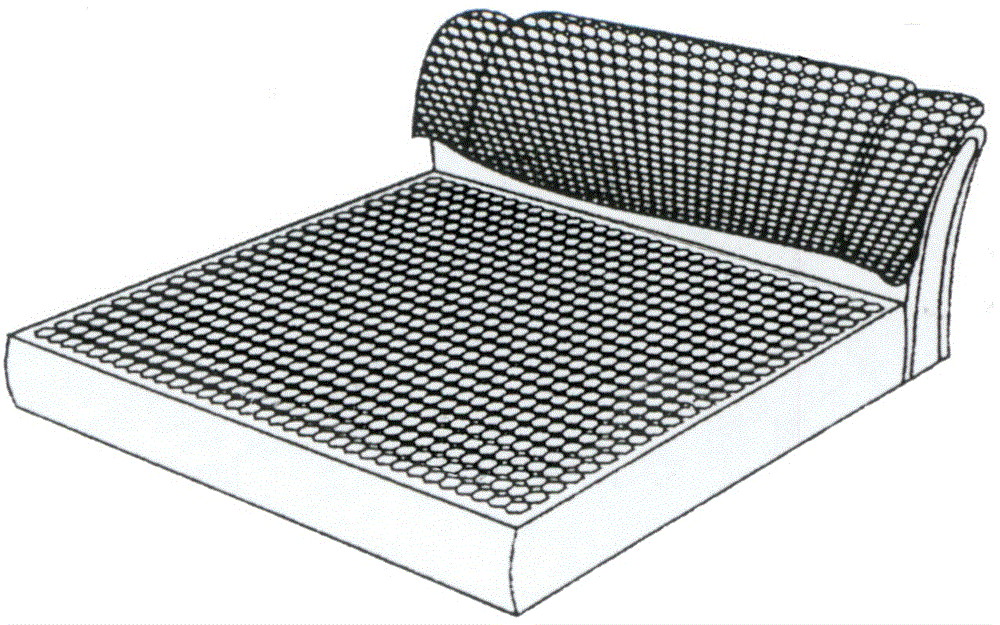
technical field [0001] The invention relates to a preparation process of a support plate, in particular to a preparation process of a honeycomb support structure. Background technique [0002] In the prior art, the support structure placed in the bed frame to support the mattress usually adopts a cross bar and a vertical bar, which are installed on the bed frame parallel to the mattress through the cross bar and the vertical bar, and then placed on the bed frame. The mattress is supported on the rails and rails. [0003] The setting of the above structure often occurs that when a certain horizontal bar or longitudinal bar is damaged, the use performance is greatly affected, and the setting of the structure leads to poor supporting effect and stability, and a short service life. Contents of the invention [0004] The purpose of the present invention is to solve the problems that the existing supporting structures adopt the structure of horizontal bars or longitudinal bars,...

Claims


Application Information

Patent Timeline
Patent Type & Authority Applications(China)
IPC IPC(8): B29D99/00
CPCB29D99/0089
Inventor 廖晓阳
Owner 成都柒柒家祥科技有限公司
Learn More