A high-efficiency power generation wheel using tire running deformation

A tire and high-efficiency technology, applied in the direction of wheels, electrical components, electromechanical devices, etc., can solve the problems of difficult tires, low power generation efficiency, different vibration and shock frequencies and uncertainties in the amount of deformation, and achieve large strokes and improve power generation efficiency. , the effect of fast reciprocating motion

Active Publication Date: 2018-07-20
汤明德
View PDF5 Cites 0 Cited by
  • Summary
  • Abstract
  • Description
  • Claims
  • Application Information

AI Technical Summary

Problems solved by technology

It uses the deformation of the tire to drive the reciprocating motion between the mover and the stator to cut the magnetic field lines to generate electricity. Since the moving direction of the mover is almost perpendicular to the direction of the tire, it consumes less energy and improves the power generation efficiency compared with other existing technologies. Due to the complexity of tire deformation, including the difference and uncertainty of deformation, tire speed, and vibration and shock frequency, how to combine tire power generation with these factors to better improve power generation efficiency is a direction that needs further research. , otherwise the power generation efficiency is not high, and tire power generation is difficult to be used in actual vehicles

Method used


Image

  • A high-efficiency power generation wheel using tire running deformation
  • A high-efficiency power generation wheel using tire running deformation
  • A high-efficiency power generation wheel using tire running deformation

Examples


Embodiment Construction

[0027] The present invention will be further described in detail below in conjunction with the drawings.

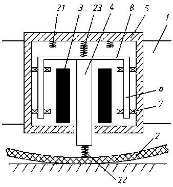
[0028] See figure 1 The present invention uses tires to deform and efficiently generate power wheels. The tires are composed of a rim 1 and a rubber carcass 2. Several sets of linear generators are provided along the circumference of the tire, and each set of linear generators includes a matched stator 3 and a mover. 4. The stator 3 is located in the casing 5, and the casing 5 is fixedly installed on the rim 1. The stator 3 is formed by winding coils on a skeleton formed by stacking silicon steel sheets or other materials, and the axis of the stator 3 is in the tire diameter direction. The mover 4 is composed of a skeleton and a permanent magnet or an excitation coil mounted on the skeleton. The two ends of the mover pass through the stator, one end passes through the casing 5 and faces the rubber carcass 2 after passing through the stator 3, and the other end is located in...


PUM


Abstract

The invention discloses an efficient power-generating wheel utilizing tire driving deformation. A plurality of linear generators are arranged on a tire along the circumferential direction; stators of the linear generators are located in a shell; the axes of the stators are located on the diameter direction of the tire; two ends of rotors penetrates out of the stators; guiding shafts are symmetrically arranged on the two sides of the rotors; the guiding shafts are arranged on the shell through bearings; two guiding shafts and rotors are integrally connected toward the central end of the tire through connecting plates; one end of each rotor penetrates out of the shell so as to be in contact with the inner bottom surface of the rubber tire all the time in the rotating process of the tire and form an axial reciprocating motion between the stators under the guiding effect of the guiding shafts following the deformation of the rubber tire at the contact point; a centrifugal force balancing mechanism is arranged in the shell and is used for adjusting the acting forces between the rotors and the rubber tire under the centrifugal forces brought by different rotating speeds. The efficient power-generating wheel utilizing tire driving deformation can obviously increase the tire power-generating efficiency and can establish an excellent basis for more quick and effective popularization of the technique.

Description

Technical field [0001] The invention relates to the improvement of the self-generation technology by using tire rotation, and belongs to the technical field of tire power generation. Background technique [0002] When the vehicle is running, the tires rotate rapidly. Some people notice the kinetic energy generated by the rotation of the tires, so research on tire power generation appears. The current understanding of tire power generation mostly rests on the piezoelectric effect and the rotation and cutting of magnetic field lines to generate electric current. The disadvantage of piezoelectric effect power generation is that the amount of power generation is very small, and the piezoelectric effect on soft materials is not obvious. The method of generating rotationally cutting magnetic lines of force in tire deformation is very complicated and difficult to achieve. Therefore, to make the tire deform to generate electricity without consuming a large amount of additional vehicle ...

Claims


Application Information

Patent Timeline
Patent Type & Authority Patents(China)
IPC IPC(8): B60B19/00H02K35/00H02K35/02B60K25/08
CPCB60B19/00B60K25/08H02K35/00H02K35/02
Inventor 汤明德
Owner 汤明德
Why Eureka
Try Eureka