Mini tiller, gearbox and steering mechanism thereof

A technology of steering mechanism and gearbox, which is applied in the field of gearboxes, and can solve the problems of large operating force of the separation mechanism, influence of output torque, and influence on return speed, etc., and achieve the effects of fast return speed, easy operation, and reduced operating intensity

Inactive Publication Date: 2017-02-22
CHONGQING WANHU MECHANICAL & ELECTRICAL PROD CO LTD
View PDF5 Cites 1 Cited by
  • Summary
  • Abstract
  • Description
  • Claims
  • Application Information

AI Technical Summary

Problems solved by technology

[0004] At present, the output of the tiller gearbox in agricultural machinery is mostly a through shaft, which makes it difficult to turn and consumes a lot of energy when running on uneven roads
In order to solve the above-mentioned problems, a small part of the shaft is divided into left and right half shafts by means of jaw clutches. The disadvantages are: since the output end of the shaft is terminal output, the torque is large, resulting in a large force to operate the separation mechanism, and It is necessary to design a special operating handle, because it is a tooth-embedded structure, it will inevitably affect the return speed, resulting in slow return
There are also some differential gears added, but in this way, the output torque of the tiller is affected by the differential during tillage, and the original tillage function is lost.

Method used


Image

  • Mini tiller, gearbox and steering mechanism thereof
  • Mini tiller, gearbox and steering mechanism thereof
  • Mini tiller, gearbox and steering mechanism thereof

Examples


Embodiment Construction

[0021] The specific embodiments of the present invention will be described in further detail below in conjunction with the accompanying drawings, but the present invention is not limited to these embodiments, and any improvement or replacement in the basic spirit of this embodiment still belongs to the claims of the present invention. scope.

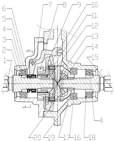
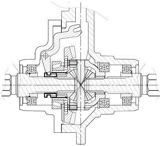
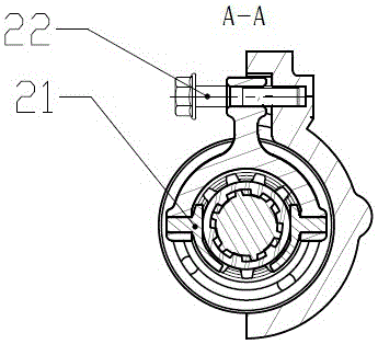
[0022] Example: such as Figure 1-4 As shown, a steering mechanism of a gearbox includes a left half shaft 1 and a right half shaft 15, and also includes a differential assembly; wherein, the differential assembly is composed of a left side gear 12, a left side gear Sleeve 11, right side shaft gear 14, planetary gear 13, planetary gear shaft 20 and differential case 17; the left side shaft gear 12 of the differential assembly is connected to the left side shaft 1 through a spline , the right side gear 14 of the differential assembly is connected to the right side shaft 15 through a spline. The steering mechanism also includes a driven ...


PUM


Abstract

The invention discloses a steering mechanism for a gearbox. The steering mechanism comprises a left half shaft (1) and a right half shaft (15), and is characterized by further comprising a differential assembly, wherein half shaft gears at both ends of the differential assembly are connected with the left half shaft (1) and the right half shaft (15) through splines; the steering mechanism further comprises a driven bevel gear (9) sleeving the left half shaft (1) or the right half shaft (15); the driven bevel gear (9) is fixedly connected with the differential assembly; the steering mechanism further comprises a clutch mechanism used for fixedly connecting the driven bevel gear (9) with the left half shaft (1) or the right half shaft (15). The steering mechanism provided by the invention can be used to reduce energy consumption and realize multifunctional tillage.

Description

[0001] Technical field: [0002] The invention relates to a gearbox of an agricultural tiller and a steering mechanism in the gearbox. [0003] Background technique: [0004] At present, the output of the tiller gearbox in agricultural machinery is mostly a through shaft, which makes it difficult to turn and consumes a lot of energy when running on uneven roads. In order to solve the above-mentioned problems, a small part of the shaft is divided into left and right half shafts by means of jaw clutches. The disadvantages are: since the output end of the shaft is terminal output, the torque is large, resulting in a large force to operate the separation mechanism, and It is necessary to design a special operating handle, because it is an interlocking structure, it will inevitably affect the return speed, resulting in slow return. There are also some increased differential gears, but in this way, the output torque of the tiller is affected by the differential during tillage, and t...

Claims


Application Information

Patent Timeline
Patent Type & Authority Applications(China)
IPC IPC(8): B60K17/16
CPCB60K17/165
Inventor 李强
Owner CHONGQING WANHU MECHANICAL & ELECTRICAL PROD CO LTD
Why Eureka
Try Eureka